Wing fold system with latch pins through multiple mating lugs

a technology of latching pins and lugs, which is applied in the direction of wing adjustment, drag reduction, etc., can solve the problems of airport gate locations and taxiway spacing, without providing adequate spacing for aircra

Active Publication Date: 2014-03-06
THE BOEING CO
View PDF6 Cites 40 Cited by
  • Summary
  • Abstract
  • Description
  • Claims
  • Application Information

AI Technical Summary

Benefits of technology

[0005]Illustrative embodiments provide for a method of a wing fold system of a wing of an aircraft is presented. The method may include preventing, via a first cam that may include a first lock of a latch, which may prevent movement of a latch pin of the latch, which may prevent movement of an unfixed portion of the wing with respect to a fixed portion of the wing, a second lock from transitioning to a second engaged position until the first lock is in a first engaged position via contact with a second cam of the second lock. Preventing, via the second cam comprised by the second lock of a latch, the first lock from transitioning away from the first engaged position until the second lock transitions away from the second engaged position.
[0006]Illustrative embodiments provide for a wing fold system of a wing of an aircraft. The system may include a first lock of a latch to prevent movement of a latch pin of the latch to prevent movement of an unfixed portion of the wing with respect to a fixed portion of the wing, the first lock comprising a first cam to prevent the second lock from transitioning to a second engaged position until the first lock is in a first engaged position via contact with a second cam of the second lock. A second lock of the latch, the second lock comprising the second cam to prevent the first lock from transitioning away from the first engaged position until the second lock transitions away from the second engaged position.

Problems solved by technology

However, taxiway spacing and gate locations for most airports were established without providing adequate spacing for aircraft with the longer wingspans that can be produced with today's technology.

Method used


Image

  • Wing fold system with latch pins through multiple mating lugs
  • Wing fold system with latch pins through multiple mating lugs
  • Wing fold system with latch pins through multiple mating lugs

Examples


Embodiment Construction

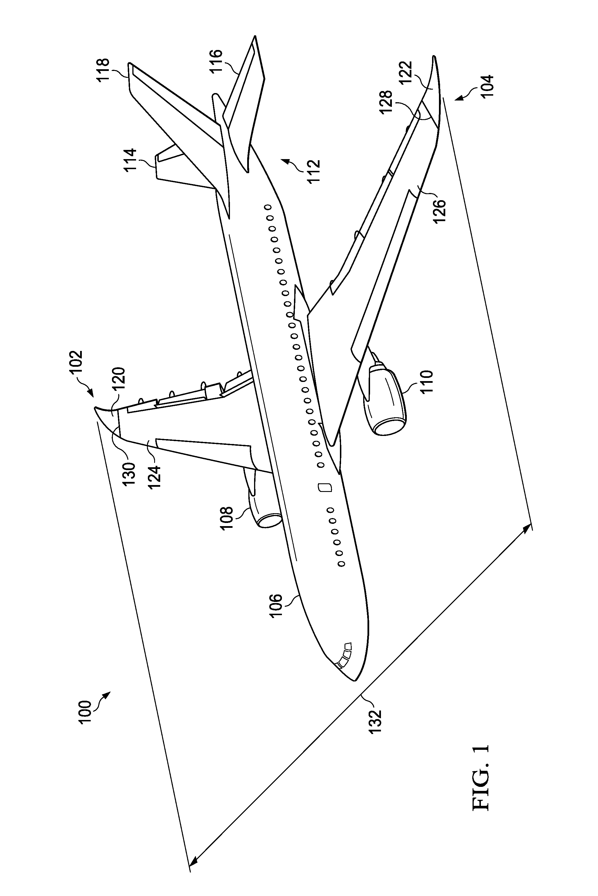
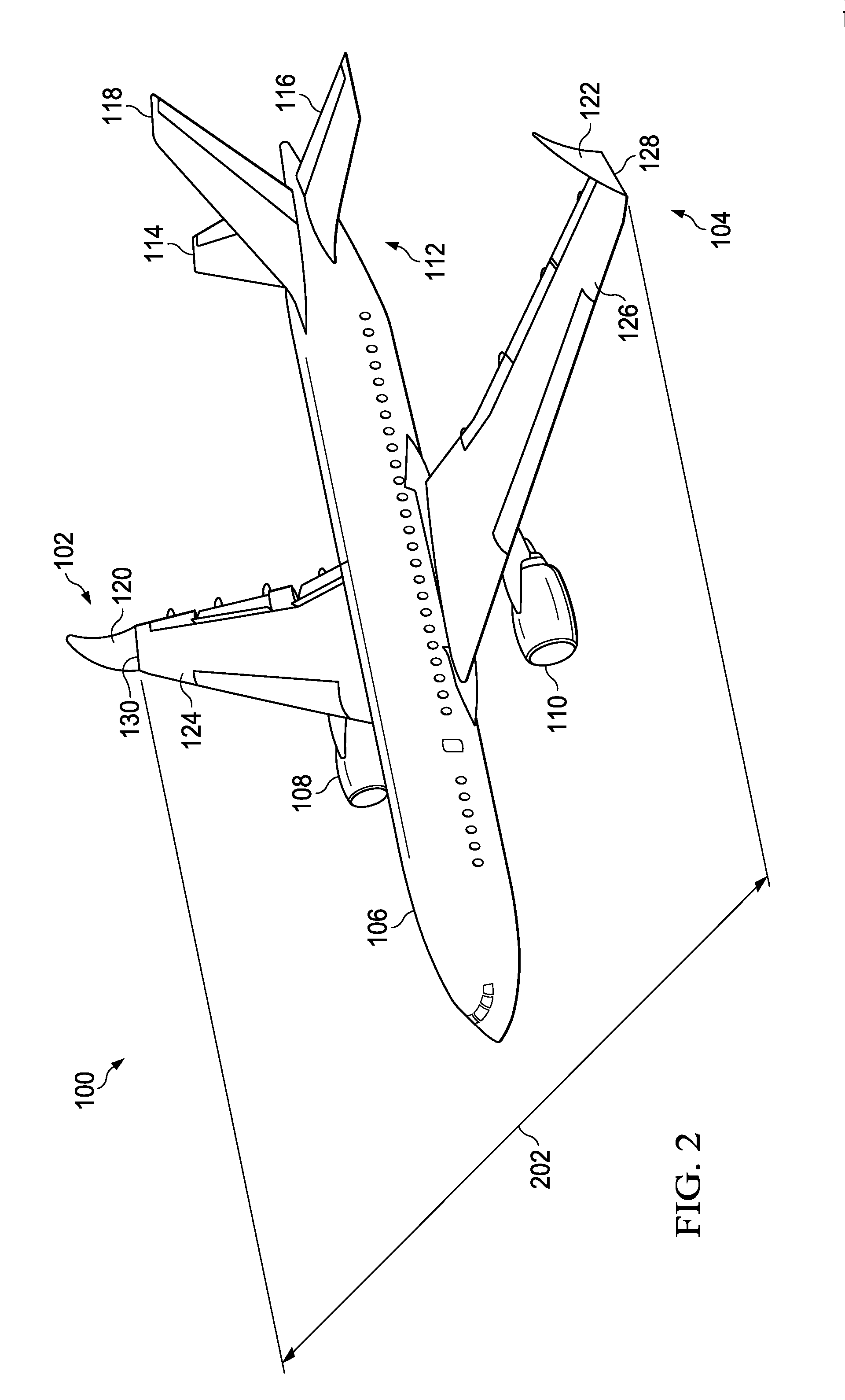
[0025]Unless otherwise noted and where appropriate, similarly named features and elements of an embodiment of one figure of the disclosure correspond to and embody similarly named features and elements of embodiments of the other figures of the disclosure. With reference now to the figures, and in particular, with reference to FIGS. 1 and 2, an illustration of a diagram of an aircraft embodying a wing fold controller of a wing fold system is depicted in accordance with an illustrative embodiment. In this illustrative example, aircraft 100 includes wing 102 and wing 104 attached to body 106; engine 108 attached to wing 102; engine 110 attached to wing 104. FIG. 1 depicts wing 102 and wing 104 of aircraft 100 in a flight position with wingspan 132. FIG. 2 depicts wing 102 and wing 104 of aircraft 100 in a folded position with wingspan 202. Wingspan 202 may be shorter than wingspan 132.

[0026]Wing 102 includes fixed portion 124 and unfixed portion 120. Fixed portion 124 may be an inboar...


PUM


Abstract

A wing fold system of a wing of an aircraft. The system may include a first lock of a latch to prevent movement of a latch pin of the latch to prevent movement of an unfixed portion of the wing with respect to a fixed portion of the wing, the first lock may include a first cam configured to prevent the second lock from transitioning to a second engaged position until the first lock may be in a first engaged position via contact with a second cam of the second lock. A second lock of the latch, the second lock may include the second cam configured to prevent the first lock from transitioning away from the first engaged position until the second lock transitions away from the second engaged position.

Description

CROSS REFERENCE AND PRIORITY[0001]The instant application claims priority to Provisional U.S. Patent Application No. 61 / 720,345, filed Oct. 30, 2012; the instant application is a continuation-in-part of U.S. patent application Ser. No. 13 / 664,416, filed Oct. 30, 2012, which is a continuation-in-part of U.S. patent application Ser. No. 13 / 251,216, filed on Oct. 1, 2011; disclosures of each of the above noted applications are incorporated herein by reference in their entirety.FIELD OF THE DISCLOSURE[0002]This disclosure relates to systems and methods for providing wings, and more specifically, to systems and methods for latching wings that enhance aircraft performance.BACKGROUND OF THE DISCLOSURE[0003]In today's commercial transport industry, it is highly desirable to design aircraft configurations that yield reduced fuel burn per seat-mile, as fuel burn per seat-mile is a metric of fuel efficiency. Efficient aircraft configurations are ever more important as fuel costs increase. Airc...

Claims


Application Information

Patent Timeline
Patent Type & Authority Applications(United States)
IPC IPC(8): B64C3/56
CPCB64C3/56Y02T50/10
Inventor GOOD, MARK STEVENKORDEL, JAN A.PIETERSEN, QUENTIN THEODORWALKER, STEVEN PAULJONES, KELLY THOMASLASSEN, MATTHEW AUGUSTHANSKEN, RICKIE
Owner THE BOEING CO
Why Eureka
Try Eureka