System and method for leak detection

a leak detection and system technology, applied in the field of leak detection, can solve the problems of unreliable detection of specific temperature on the temperature distribution as an indicator of leakage or spillage, labor-intensive sniffer systems, and inability to provide robust solutions for the broad range of fluids, so as to achieve the effect of reducing false alarms

Active Publication Date: 2014-03-06
CRITICAL IMAGING
View PDF6 Cites 15 Cited by
  • Summary
  • Abstract
  • Description
  • Claims
  • Application Information

AI Technical Summary

Benefits of technology

[0006]This disclosure describes embodiments of systems and methods that can identify and image leaks and spills while simultaneously viewing the unchanging background. These embodiments provide a normal dynamic range thermal image that can be colorized to identify the leak or spill as the leak or spill develops over time. As set forth more below, the systems and methods can minimize false alarms, addressing potential issues that arise in connection with meteorological events (e.g., precipitation), noise sources, and relative motion between the image capture device and the scene.

Problems solved by technology

Although accurate to generate gas concentration readings, these sniffer systems are labor-intensive and require the sensing devices to be in close proximity to the components under observation.
Unfortunately, thermal imaging does not provide a robust solution for the broad range of fluids (e.g., gas and liquids) that may require in-situ detection technology.
For example, detection of specific temperatures on the temperature distributions as an indicator of leakage or spills is likely unreliable because the absolute or radiation temperatures of spilled fluids is often unknown.
Moreover, conventional controls (e.g., gain and level controls) and other color algorithms found on thermal imaging systems do not provide adequate visualization of leaks and spills because of the low signal levels and broad dynamic temperature range found in scenes under observation.
Thermal imaging is particularly difficult for materials that exhibit particularly low thermal signatures, e.g., gasses.
Difference imaging and related techniques do not, however, comport with continually changing ambient conditions.
Nor do these techniques deal well with changes in the sensitivity of thermal imaging equipment.
Rather, changes in the scene and / or equipment can give rise to spurious signals that are indistinguishable from signals that indicate that a spill or leak is underway.
In this case, problems can arise because the current image must show the component under observation in exactly the same orientation and view as the component that is found in the reference image.

Method used


Image

  • System and method for leak detection
  • System and method for leak detection
  • System and method for leak detection

Examples


Embodiment Construction

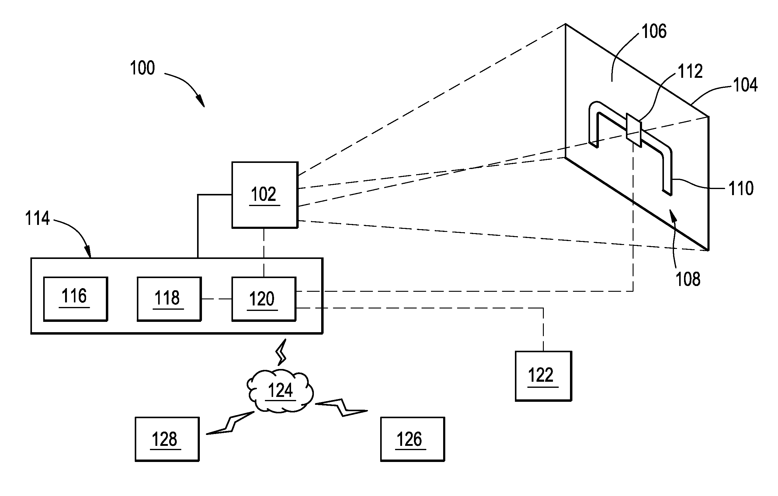
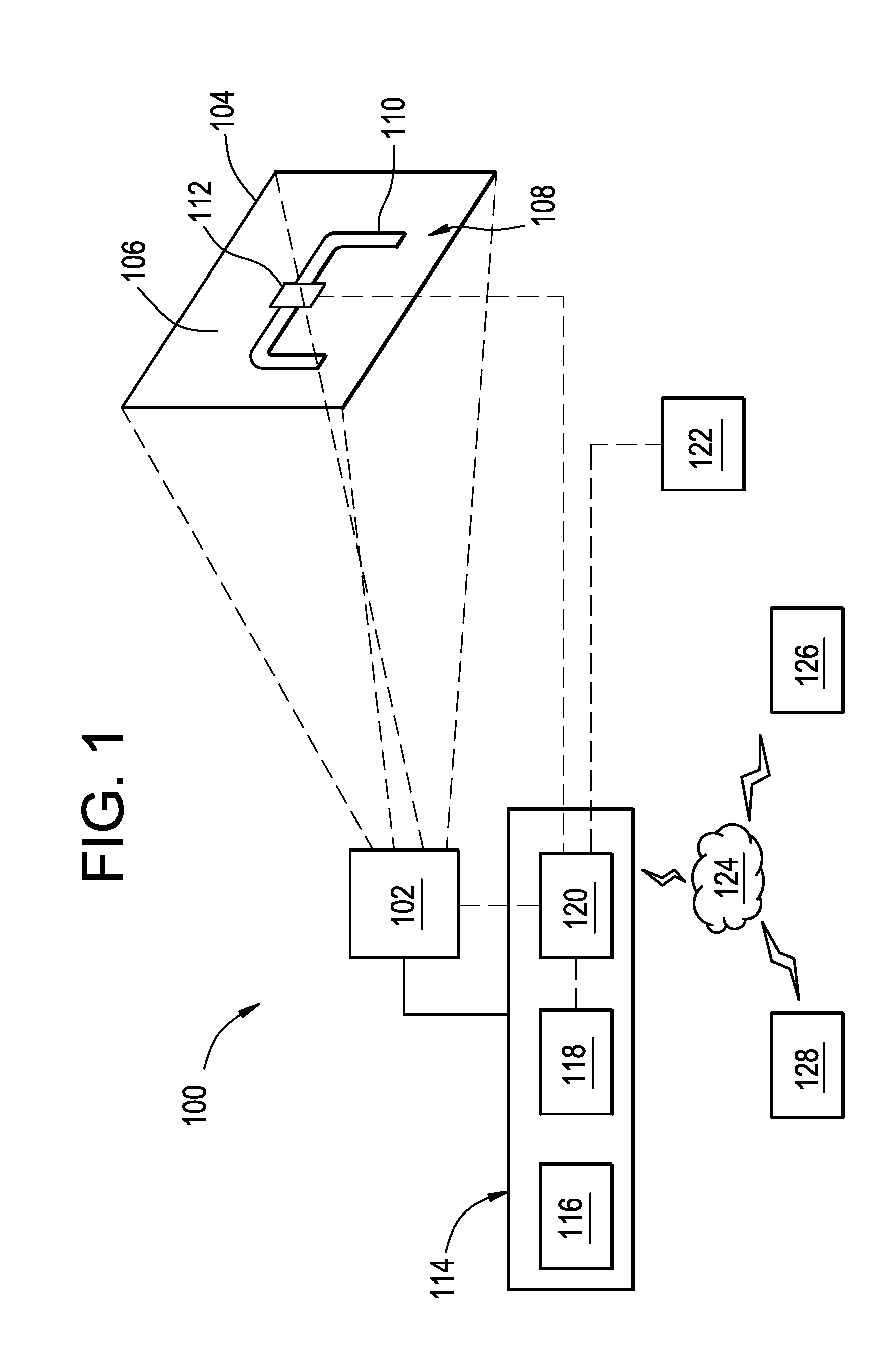
[0021]FIG. 1 illustrates a schematic diagram of an example of an optical detection system 100 that can detect effluent that occurs at targets under observation, e.g., piplelines. The optical detection system 100 includes an image capture device 102 with a field of view 104 that captures image data of a scene 106. In the example of FIG. 1, the scene 106 includes a target 108 with one or more sections of a pipe 110 with a coupling valve 112 secured thereto. The optical detection system 100 also includes one or more components 114, which may include an image processor 116, a display 118, and a controller 120. However, although shown as separate components 114, this disclosure further contemplates configurations of the image capture device 102 that may include features and functions of one or more of the display 118 and / or components of the image processor 116. Examples of the controller 120 may communicate with the image capture device 102 and the display 118, as well as with a remote ...


PUM


Abstract

This disclosure describes embodiments of systems and methods that can identify and image leaks and spills while simultaneously viewing the unchanging background. In one embodiment, the system includes an image capture device and an image processing device, which receives a first image frame and a second image frame from the image capture device. The image processing device can identify a region of variation in the second image frame that corresponds to a change in a scene parameter (e.g., temperature) as between the first image frame and the second image frame. These embodiments provide a normal dynamic range thermal image that can be colorized to identify the leak or spill as the leak or spill develops over time. The systems and methods can minimize false alarms, addressing potential issues that arise in connection with meteorological events (e.g., precipitation), noise sources, and relative motion between the image capture device and the scene.

Description

BACKGROUND OF THE INVENTION[0001]The subject matter disclosed herein relates to leak detection and, in particular, to systems and methods for detection and display of effluent using optical detection systems, e.g., thermal imaging systems.[0002]Many industries seek efficient means to perform in-situ detection of leaks and other component failures that allow effluent to discharge, e.g., from pipes, tanks, etc. By detecting leaks early, these industries can avoid the discharge of large amounts of materials, many of which may be carcinogenic, toxic, flammable, and explosive. Early detection can reduce the cost of necessary clean-up and decontamination, as well as limit repair costs and improve profits by stemming the flow of material that is lost, e.g., by leakage from a pipeline. In fact, regulations in some industries often require constant monitoring of equipment to control and reduce the incidence of leakage.[0003]One type of in-situ detection systems have sensing devices that dete...

Claims


Application Information

Patent Timeline
Patent Type & Authority Applications(United States)
IPC IPC(8): G06K9/00
CPCG08B21/20G06V20/52
Inventor KNAUTH, JONATHAN PATRICK
Owner CRITICAL IMAGING
Why Eureka
Try Eureka