Target acquisition and tracking system

a tracking system and target technology, applied in the field of target acquisition and tracking system, can solve problems such as hotness, achieve the effects of low false alarm rate, avoid depletion, and high effective probability of detection

Inactive Publication Date: 2009-10-22
TREX ENTERPRISES CORP
View PDF3 Cites 71 Cited by
  • Summary
  • Abstract
  • Description
  • Claims
  • Application Information

AI Technical Summary

Benefits of technology

[0009]Although only a small portion of the total trajectory may be captured, the very accurate position information permits extrapolation to determine the launch point of the projectile.
[0010]A preferred sensor system designed to detect small arms fire and to control defensive counter-fire responses from helicopters or other airborne platforms has a combination of the following features: (a) wide angle surveillance coverage, (b) high effective probability of detection, even at low signal to noise ratios, (c) low false alarm rates to avoid depletion of the defensive gun's ammunition, (d) range accuracy of one or two meters, (e) angular accuracies of a few hundred micro-radians, (f) ability to communicate threat information in real-time via standard digital computer interfaces and (g) be very difficult to countermeasure. The sensor should be capable of being netted to other nearby combat airborne assets with a real time communication link to provide wide angles of defensive counter-fire to threat shooting positions. These stressing detection and tracking requirements can be realized by using a mid-wave infrared camera coupled to a very fast step-stare system with good pointing accuracy and have some capability for background subtraction (for clutter rejection). A laser rangefinder in the tracker is also required to provide the shooter ground position including range and the in flight munitions (such as bullets and rocket propelled grenades) range metric to minimize false alarms caused by flash-bang countermeasures or explosions.
[0011]Improvement to the systems described in the '509 application include a dual mirror 40 degree field of regard scanning mirror, a special azimuth mount, laser stabilization techniques, clutter rejection techniques, image processing improvements and a very light weight rigid scanning mirror design.

Problems solved by technology

Projectiles of interest are typically traveling at a substantial fraction of the speed of sound or even faster than the speed of sound, and therefore become hot due to aerodynamic heating.

Method used


Image

  • Target acquisition and tracking system
  • Target acquisition and tracking system
  • Target acquisition and tracking system

Examples


first preferred embodiment

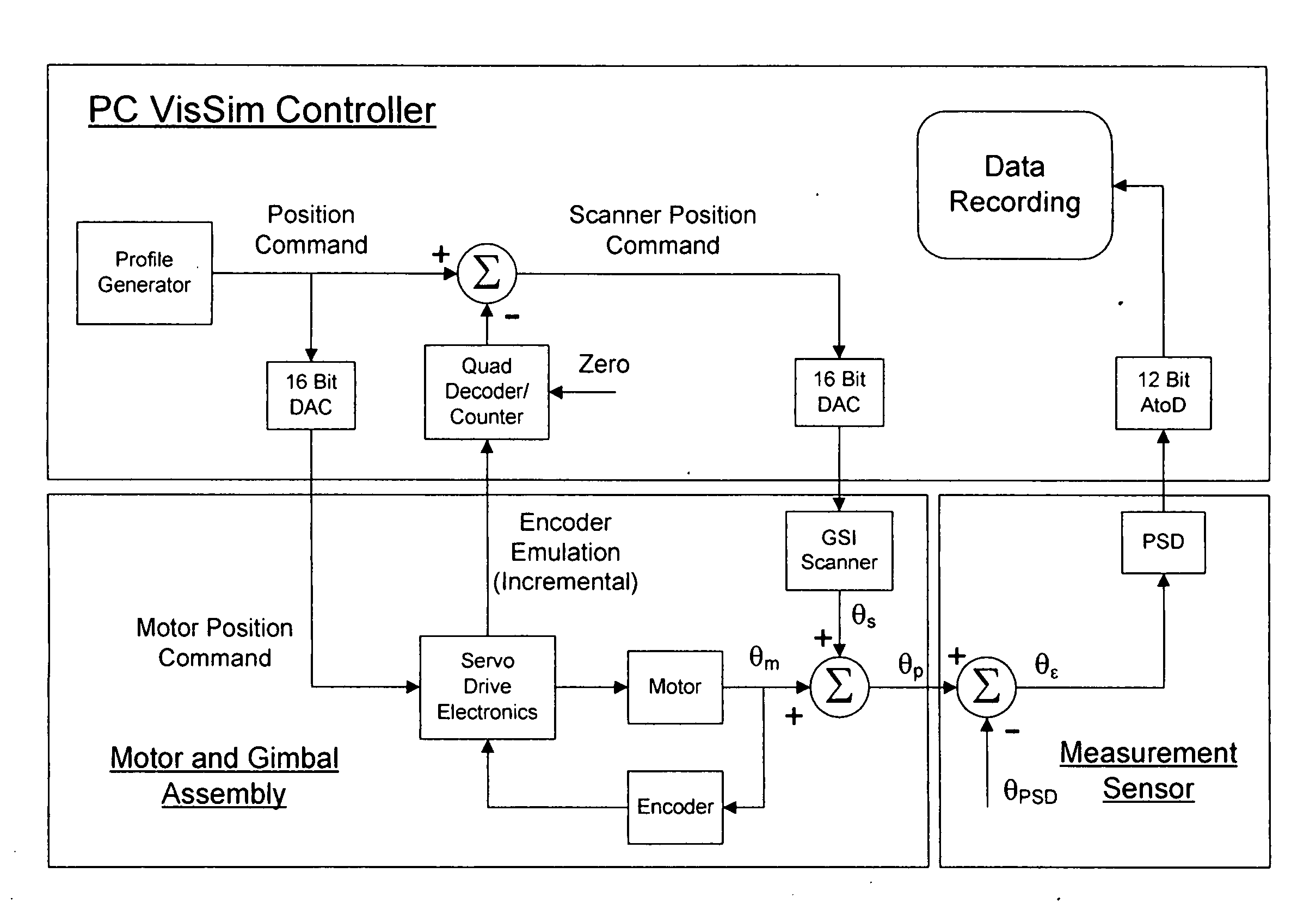
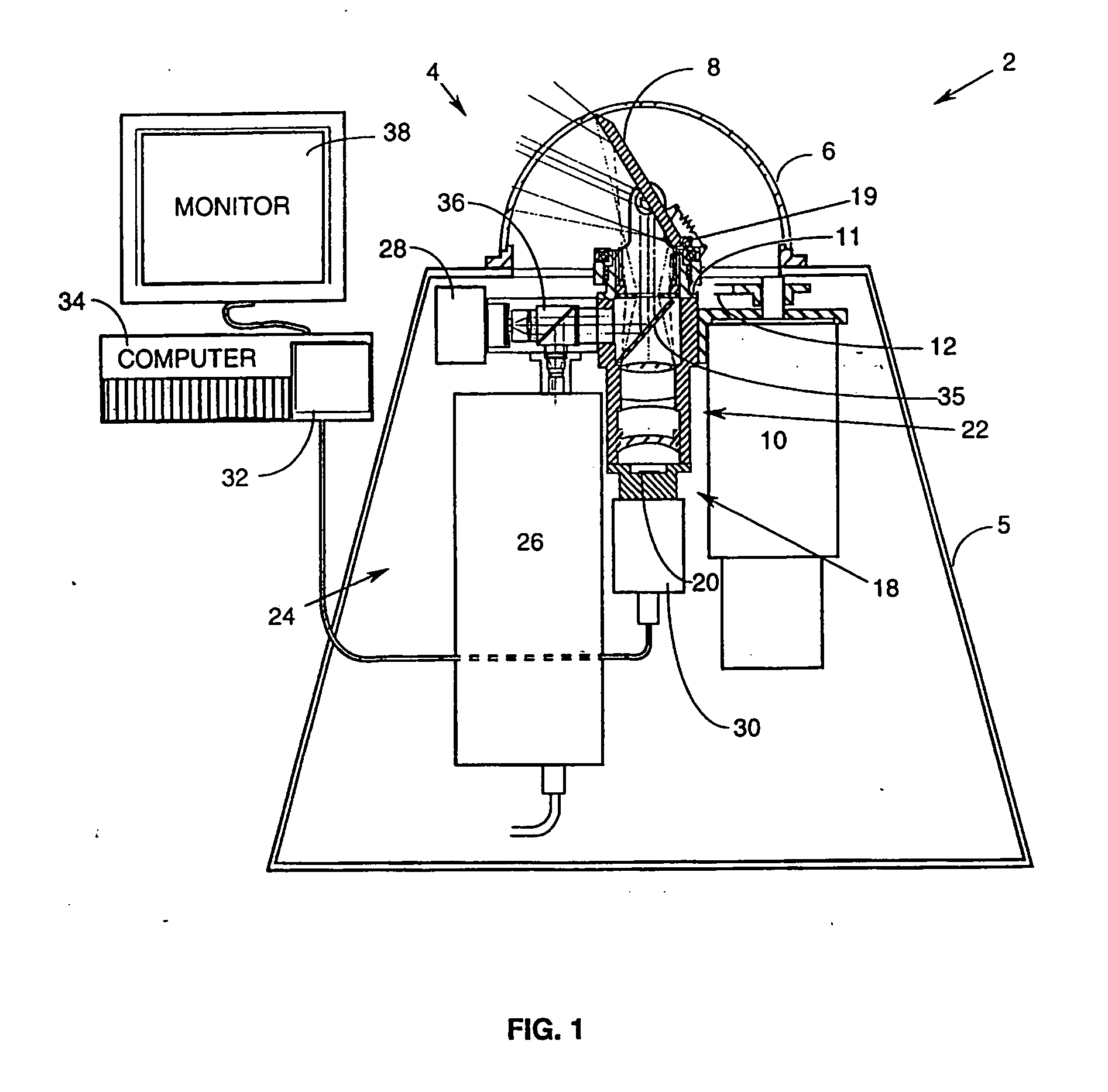
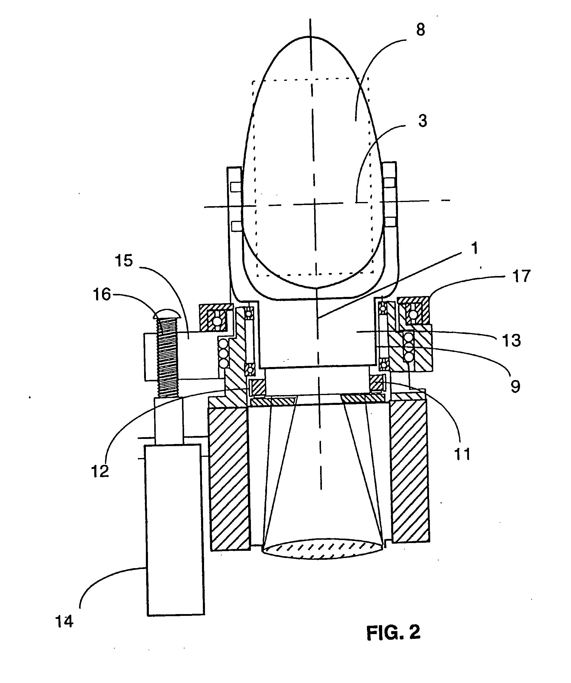
[0027]A first preferred embodiment is a third generation prototype Rapid Target Acquisition and Tracking System (called “RTATS”), which is designed to be vehicle mounted such as a (High Mobility Multi-Wheeled Vehicle) HMMWV to support defensive tactical weapons. Its design allows it to be used in helicopter carry experiments to detect rocket flights from the air. It is to conduct ground surveillance for threats such as rockets, mortars, artillery, RPG's and guided tactical missiles. The system provides surveillance and precision 3-D tracking sensor for active countermeasure weapon systems. This embodiment, as currently configured, serves as a helicopter baseline sensor suite to address and evaluate the bullet and RPG detection and tracking requirements for precision counter-fire. Its operational ranges are consistent with combat helicopters flying close to the ground in complex background environments. Specific tracking systems are described in detail below.

[0028]Specifications for ...


PUM


Abstract

A projectile tracking system for acquiring and precisely tracking a projectile in flight in order to reveal the source from which the projectile was fired. The source is revealed by the back projection of a 3-dimensional track file. In preferred embodiments the system is installed on a vehicle, such as an un-manned blimp or other aircraft, road vehicle or ship, for locating and destroying small arms fire directed at the vehicle. A kill system may also be included on the vehicle to destroy the source of the projectile.

Description

CROSS REFERENCE TO RELATED APPLICATIONS[0001]This application is a continuation in part of U.S. patent application Ser. No. 11 / 184,509 filed Jul. 18, 2005 and claims the benefit of Provisional Patent Application Ser. No. 61 / 066,027 filed Feb. 15, 2008.FEDERALLY SPONSORED RESEARCH[0002]This invention was made in the course of work under Contract No. FA9200-05-C-0182, with the United States Air Force, and Contract No. N00014-04-M-0204, with the United States Navy, Contract Nos. W9115U-06-C-003, W31P4Q-05-C-0295 and DAA H01-02-C-0031 and the United States Government has rights in the invention.FIELD OF THE INVENTION[0003]This invention relates to systems providing protection against small arms fire such as rifles and rocket powered grenades and especially to such systems providing such protection for aircraft, road vehicles and ships.BACKGROUND OF THE INVENTION[0004]During the past few years terrorist threats have increased dramatically and tremendous efforts have been made to counter ...

Claims


Application Information

Patent Timeline
Patent Type & Authority Applications(United States)
IPC IPC(8): F41G5/08G06F19/00
CPCF41G3/147G01S3/7864G02B26/0816G01S17/66G02B23/02G01S17/023G01S17/86
Inventor MELNYCHUK, STEVEFOOTE, WILLIAMZHAO, ZHONG QUAN
Owner TREX ENTERPRISES CORP
Why Eureka
Try Eureka