Method for fabricating well-aligned zinc oxide microrods and nanorods and application thereof

a technology of zinc oxide microrods and nanorods, which is applied in the direction of semiconductor/solid-state device manufacturing, basic electric elements, electric apparatus, etc., can solve the problems of high complex and difficult process of these methods, and inability to reduce the production cost of zinc oxide (zno) microrods/nanorods, etc., to achieve less processing conditions, less difficulty, and low cos

Inactive Publication Date: 2014-03-06
NAT TAIWAN UNIV
View PDF6 Cites 9 Cited by
  • Summary
  • Abstract
  • Description
  • Claims
  • Application Information

AI Technical Summary

Benefits of technology

[0010]Therefore, the present invention provides a method for fabricating well-aligned zinc oxide (ZnO) microrods / nanorods and this method having advantages of less processing condition requirements, less difficulty and low cost is provided in this invention instead of the conventional method having much processing condition requirements, much difficulty and high cost, to form straighter zinc oxide (ZnO) microrods / nanorods on a common substrate. The zinc oxide (ZnO) microrods / nanorods, which are fabricated this method of present invention, can be used as an epitaxial center to produce high quality optical devices or photoelectronic devices.

Problems solved by technology

Therefore, the processes of these methods are more complicated and more difficult, and they need apparatuses which can provide these critical processing conditions.
Most of these apparatuses are expensive and thereby the production cost of zinc oxide (ZnO) microrods / nanorods is too high to be decreased.
Furthermore, when the zinc oxide (ZnO) microrods / nanorods are fabricated by these methods, there are some wrinkles or grains forming on the surface of the seed layer of the zinc oxide microrods / nanorods.
It results in uneven surface of the seed layer, and the uneven surface of the seed layer further causes generation of oblique and crookedness of the zinc oxide microrods / nanorods formed after the seed layer.
It makes a bad impact on the quality of these zinc oxide microrods / nanorods and even on the quality of the optical devices or photoelectric devices, which are produced by these zinc oxide microrods / nanorods in following process, because these zinc oxide microrods / nanorods are not well-aligned enough.
Besides, following process of forming zinc oxide microrods / nanorods needs more critical process conditions because the seed layer is not even or planar enough.
Therefore, it results in the increasing difficulty of producing the zinc oxide microrods / nanorods.

Method used


Image

  • Method for fabricating well-aligned zinc oxide microrods and nanorods and application thereof
  • Method for fabricating well-aligned zinc oxide microrods and nanorods and application thereof
  • Method for fabricating well-aligned zinc oxide microrods and nanorods and application thereof

Examples


Embodiment Construction

[0016]The detailed description of the present invention will be discussed in the following embodiments, which are not intended to limit the scope of the present invention, and can be adapted for other applications. While drawings are illustrated in detail, it is appreciated that the quantity of the disclosed components may be greater or less than that disclosed, except where expressly restricting the amount of the components.

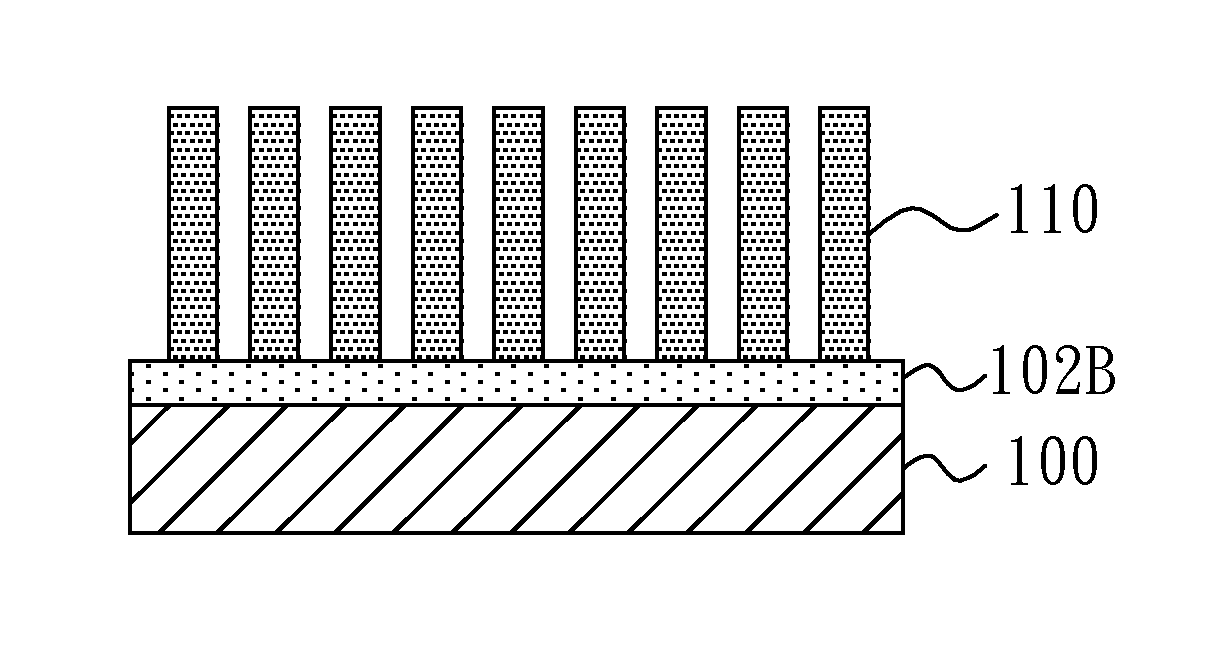
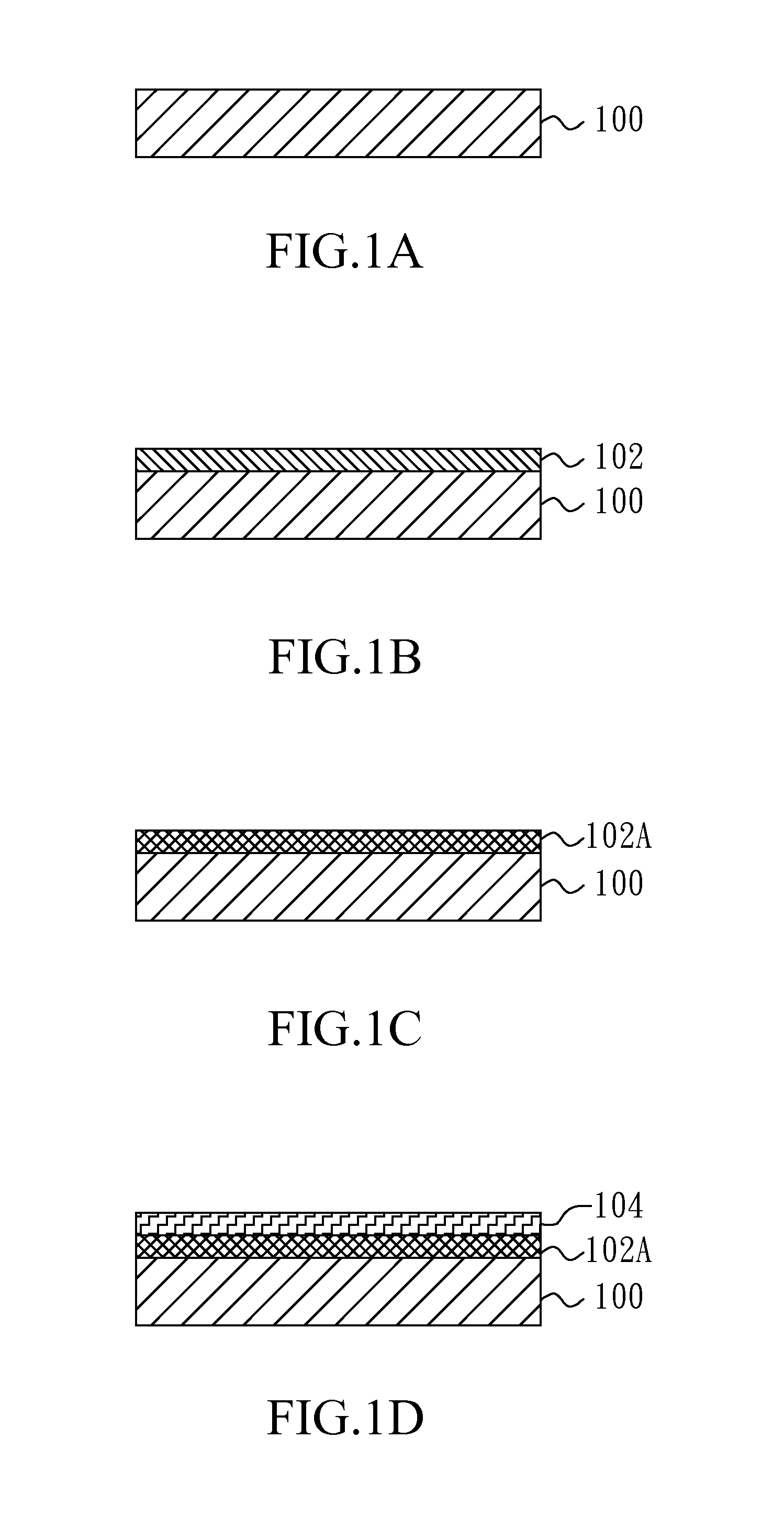
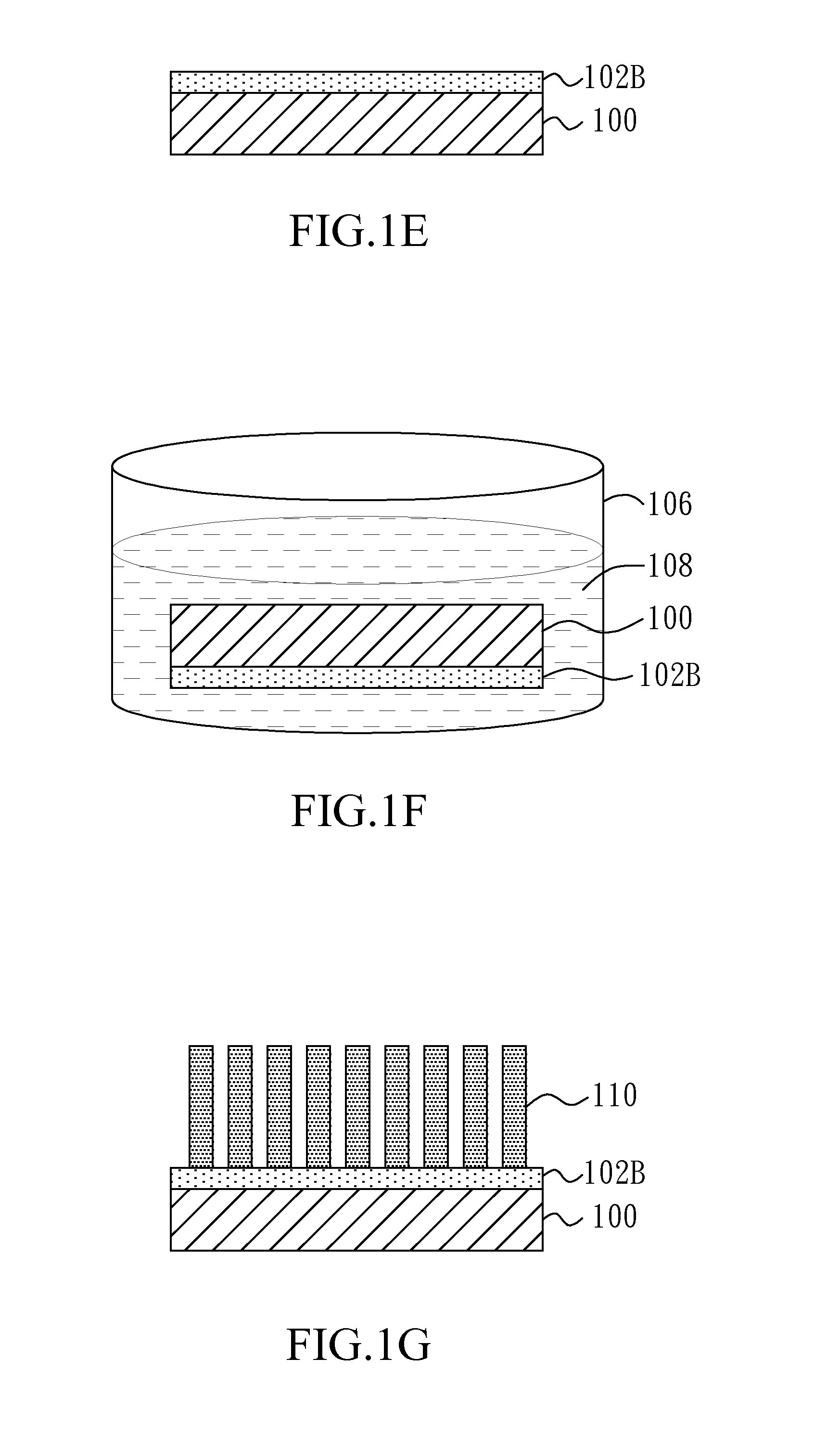
[0017]FIG. 1A to FIG. 1G show a method for fabricating well-aligned zinc oxide (ZnO) microrods / nanorods in accordance with an embodiment of the present invention, and they are a series of cross-section drawings illustrating the process of this method and different steps of this method. Referring to FIG. 1A, first, a substrate 100 is provided wherein the substrate 100 is a metal substrate, a silicon substrate, a quartz substrate, a glass substrate, a sapphire substrate, or a flexible plastic substrate. Then, a cleaning step is performed. In this cleaning step, th...


PUM

PropertyMeasurementUnit
temperatureaaaaaaaaaa
process timeaaaaaaaaaa
diametersaaaaaaaaaa

Abstract

The present invention relates to a method for fabricating well-aligned zinc oxide microrods and nanorods and application thereof and particularly relates to a method for fabricating well-aligned zinc oxide microrods and nanorods on a general substrate by hydrothermal method and application thereof.

Description

CROSS-REFERENCE TO RELATED APPLICATIONS[0001]The entire contents of Taiwan Patent Application No. 101131537, filed on Aug. 30, 2012, from which this application claims priority, are incorporated herein by reference.BACKGROUND OF THE INVENTION[0002]1. Field of the Invention[0003]The present invention relates to a method for fabricating well-aligned zinc oxide (ZnO) microrods / nanorods and application thereof and particularly relates to a method for fabricating well-aligned zinc oxide (ZnO) microrods / nanorods by hydrothermal method and application thereof.[0004]2. Description of Related Art[0005]Currently, although lots of methods for forming well-oriented and large zinc oxide (ZnO) microrods / nanorods on common substrate have been developed, most of these methods are performed by Metal-Organic Chemical Vapor Deposition (MOCVD) or other growing process for forming zinc oxide (ZnO) microrods / nanorods. Most of these methods need to be performed under critical processing conditions, such a...

Claims


Application Information

Patent Timeline
Patent Type & Authority Applications(United States)
IPC IPC(8): H01L21/02
CPCH01L21/0259H01L21/0237H01L21/02472H01L21/02554H01L21/02603H01L21/02628H01L21/02645H01L21/02658
Inventor LIN, CHING-FUHSU, HUA-LONG
Owner NAT TAIWAN UNIV
Why Eureka
Try Eureka