
Apparatus For Footwear-Embedded Mechanical Energy Harvesting System Based On Dual-Loop Channel

a technology of mechanical energy harvesting and accessories, applied in the direction of uppers, influence generators, bootlegs, etc., can solve the problems of limited service time, affecting the advancement of many electronics, and not greatly increasing their energy density

Inactive Publication Date: 2014-03-13
KRUPENKIN THOMAS NIKITA +1
View PDF14 Cites 30 Cited by
  • Summary
  • Abstract
  • Description
  • Claims
  • Application Information

AI Technical Summary

Benefits of technology

The present invention is a new energy harvesting device that uses hydraulic actuation to create a continuous, revolving motion of a chain of energy-producing elements within a channel. The device is designed to efficiently convert a unidirectional flow of fluid into a smooth, continuous motion. This patent addresses existing needs in the art and provides an improved solution for energy harvesting.

Problems solved by technology

Although battery quality has substantially improved over the last two decades, their energy density has not greatly increased.
At the present time, however, factors such as cost, weight, limited service time and waste disposable problems (all intrinsic to electrochemical batteries) are impeding the advance of many areas of electronics.
The problem is especially acute in the portable electronics space, where rapidly growing performance and sophistication of mobile electronic devices lead to ever-increasing power demands that electrochemical batteries are unable to meet.
High-power harvesting of mechanical energy is a long-recognized concept which has not been commercialized in the past due to the lack of a viable energy harvesting technology.
Traditional methods of mechanical-to-electrical energy conversion such as electromagnetic, piezoelectric, or electrostatic do not allow effective direct coupling to the majority of high-power environmental mechanical energy sources.
Bulky and expensive mechanical or hydraulic transducers are often required to convert a broad range of aperiodic forces and displacements typically encountered in nature into a form that is accessible for conversion using those methods.
However, the energy generation methods disclosed in these various references are not free from some shortcomings.

Method used


Image

  • Apparatus For Footwear-Embedded Mechanical Energy Harvesting System Based On Dual-Loop Channel
  • Apparatus For Footwear-Embedded Mechanical Energy Harvesting System Based On Dual-Loop Channel
  • Apparatus For Footwear-Embedded Mechanical Energy Harvesting System Based On Dual-Loop Channel

Examples


Embodiment Construction

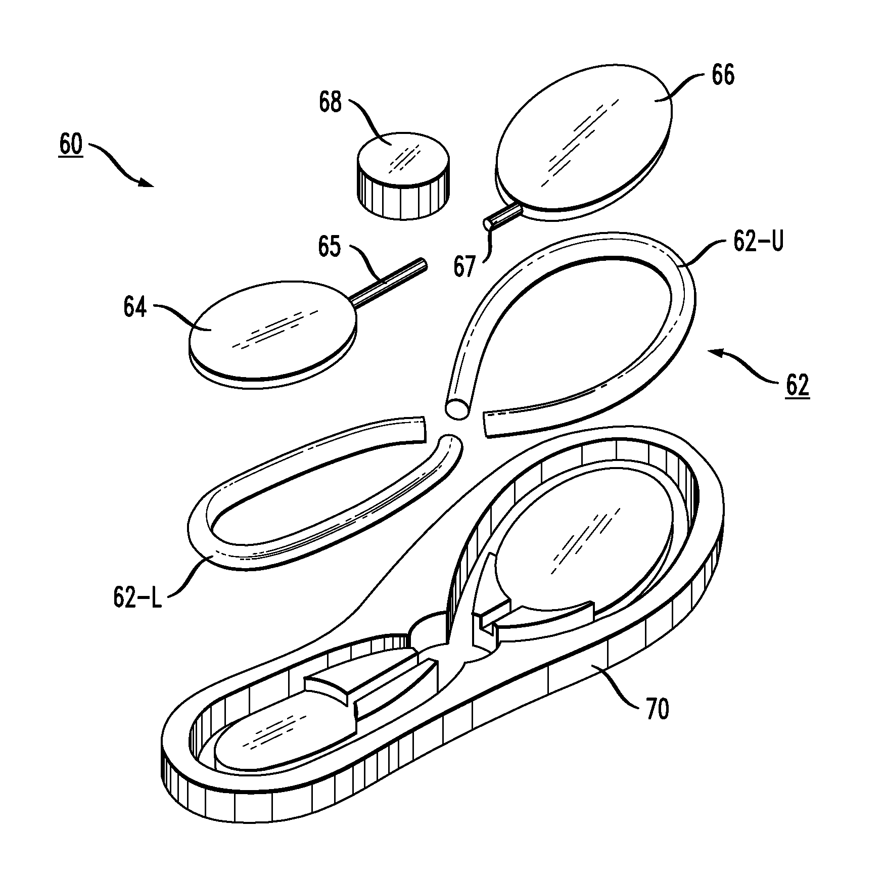
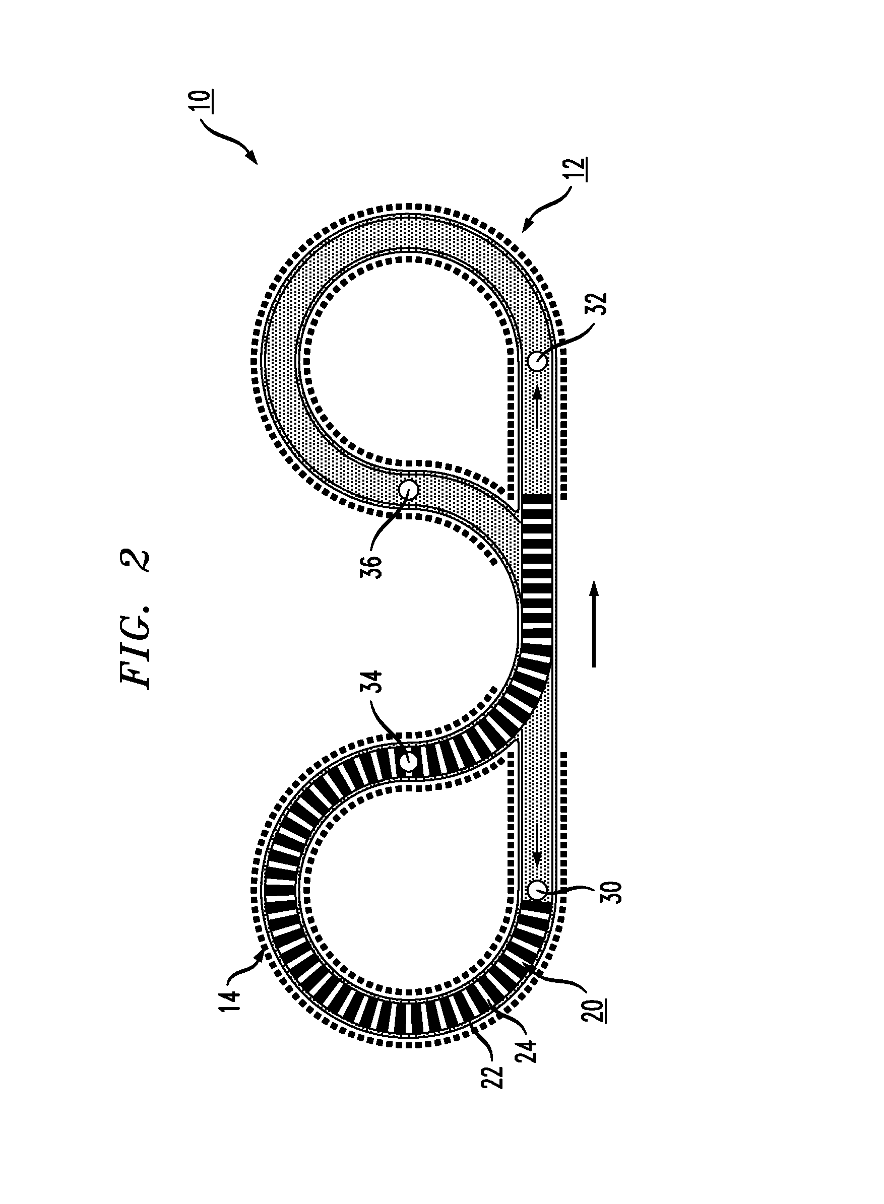
[0027]Prior to describing the particulars associated with a dual-loop channel topology for providing continuous motion of an energy-producing chain within an energy-producing channel, a basic overview of an exemplary energy harvesting mechanism based on human locomotion will be provided.

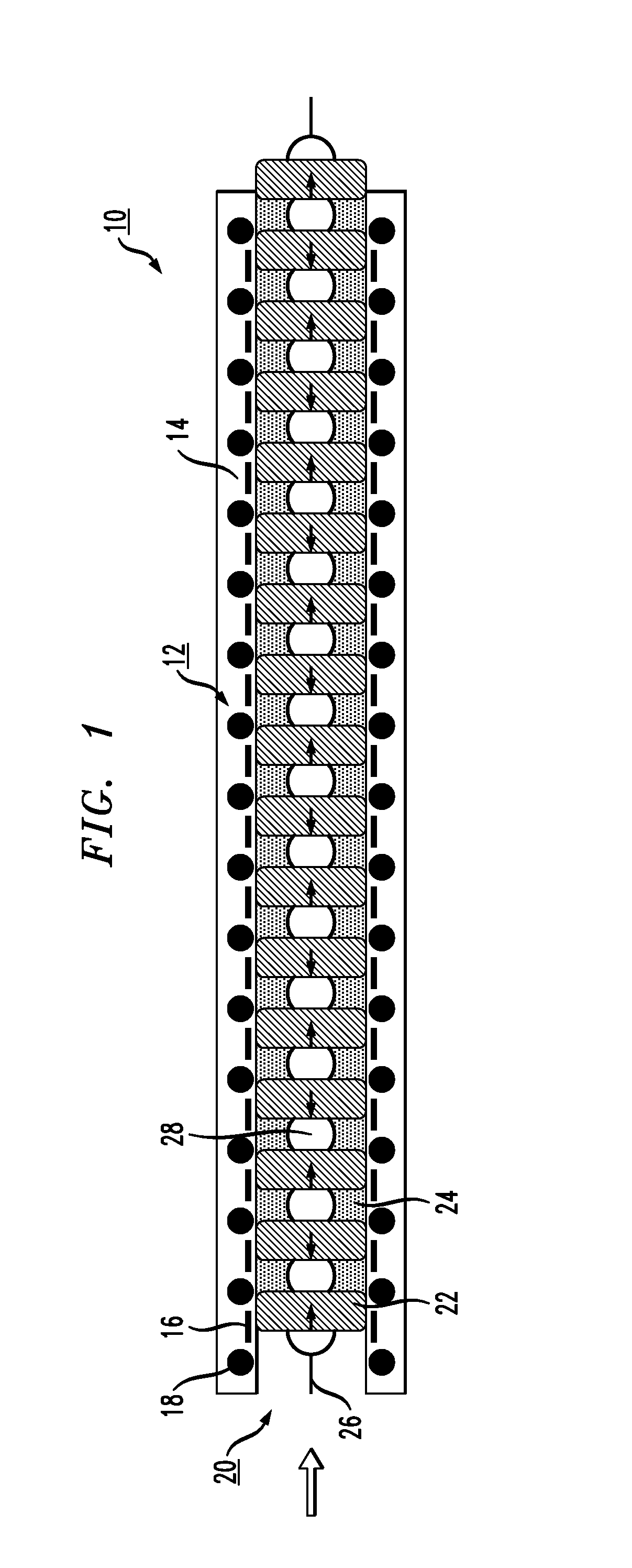
[0028]FIG. 1 illustrates a portion of an exemplary embodiment of an energy harvesting arrangement 10, which includes a flexible energy-producing channel 12 and a flexible energy-producing chain 20. Flexible energy-producing channel 12 is shown as including energy-producing elements 14, in this case a plurality of dielectric-coated electrodes 16 and a separate plurality of conductive coils 18. As shown, dielectric-coated electrodes 16 and conductive coils 18 are disposed in an alternating pattern along the length of energy-producing channel 12 (these elements may be embedded within the material forming channel 12, or disposed along an inner edge thereof).

[0029]Flexible energy-producing chain 20 compri...


PUM


Abstract

An energy harvesting apparatus is described that utilizes hydraulic actuation and creates a continuous, revolving motion of a chain of energy-producing elements within an energy-producing channel (the channel being in the form of a tube, for example). In particular, the arrangement of the present invention is based upon a specially-designed dual-loop channel topology that allows for efficient conversion of a unidirectional flow of a fluid entering the energy-producing channel into a smooth, continuous revolving motion of a chain of energy-producing elements within the channel.

Description

CROSS-REFERENCE TO RELATED APPLICATIONS[0001]This application claims the benefit of U.S. Provisional Application No. 61 / 700,359 filed on Sep. 13, 2012, and herein incorporated by reference.BACKGROUND OF THE INVENTION[0002]Currently, the majority of autonomous and mobile electronic systems are powered by electrochemical batteries. Although battery quality has substantially improved over the last two decades, their energy density has not greatly increased. At the present time, however, factors such as cost, weight, limited service time and waste disposable problems (all intrinsic to electrochemical batteries) are impeding the advance of many areas of electronics. The problem is especially acute in the portable electronics space, where rapidly growing performance and sophistication of mobile electronic devices lead to ever-increasing power demands that electrochemical batteries are unable to meet.[0003]One of the technologies that holds great promise to substantially alleviate the curr...

Claims


Application Information

Patent Timeline
IPC IPC(8): A43B3/00H02N1/08
CPCH02N1/08A43B3/0015A43B13/203A43B13/206H02N11/002A43B3/38
Inventor KRUPENKIN, THOMAS NIKITATAYLOR, JOSEPH ASHLEY
Owner KRUPENKIN THOMAS NIKITA
Learn More