Friction reduction assembly for a downhole tubular, and method of reducing friction

a friction reduction and assembly technology, applied in the direction of survey, sealing/packing, borehole/well accessories, etc., can solve the problems of insufficient initiating snubbing force, inability to reduce and the tubular may reach the point of “locking up” , to achieve the effect of reducing friction between the tubular and the surrounding casing or the borehol

Active Publication Date: 2014-03-13
BAKER HUGHES INC
View PDF3 Cites 50 Cited by
  • Summary
  • Abstract
  • Description
  • Claims
  • Application Information

AI Technical Summary

Benefits of technology

[0004]A friction reduction assembly for a downhole tubular, the friction reduction assembly includes an electrically activated friction reduction sub including: a flowbore fluidically connected to a flowbore of the tubular and remaining open for fluid flow therethrough during both acti

Problems solved by technology

When coiled tubing is conveyed in highly deviated, long horizontal, lateral, up-dip, and even vertical boreholes, the tubing may reach a point of “lock-up” whereby the surface initiated snubbing force is insufficient to overcome the frictional forces between the coiled tubing and the casing or fo

Method used


Image

  • Friction reduction assembly for a downhole tubular, and method of reducing friction
  • Friction reduction assembly for a downhole tubular, and method of reducing friction
  • Friction reduction assembly for a downhole tubular, and method of reducing friction

Examples


Embodiment Construction

[0019]A detailed description of one or more embodiments of the disclosed apparatus and method are presented herein by way of exemplification and not limitation with reference to the Figures.

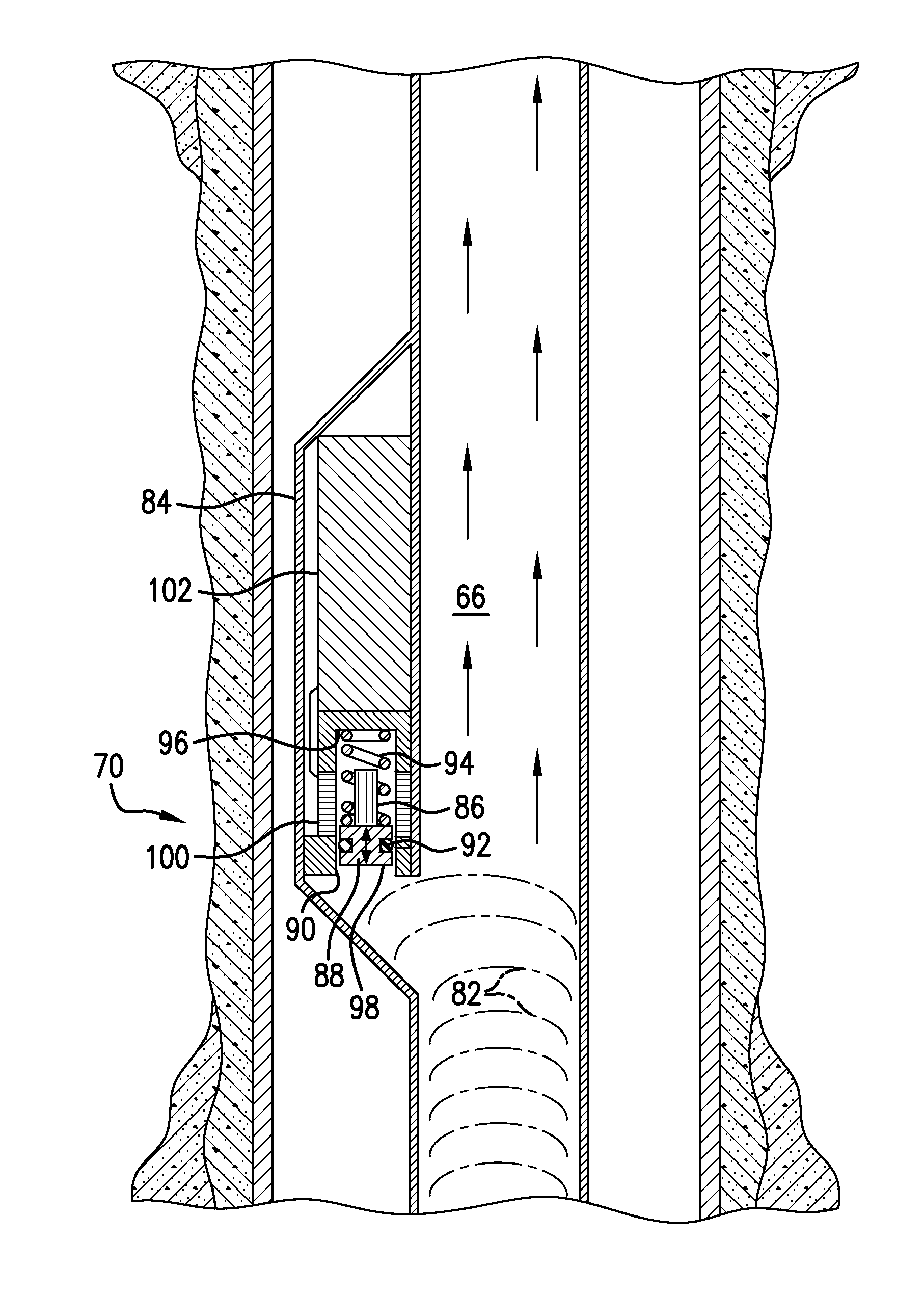
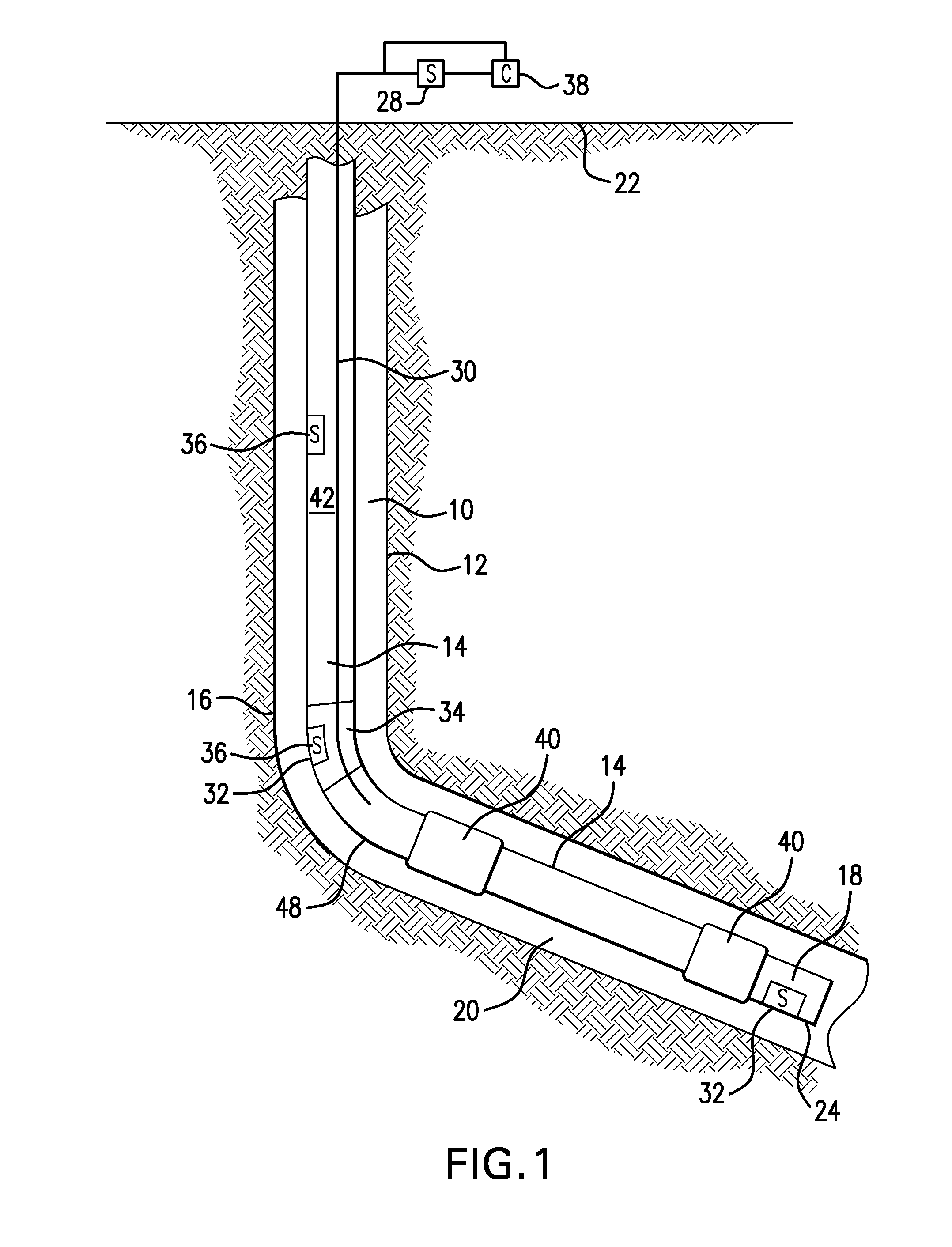
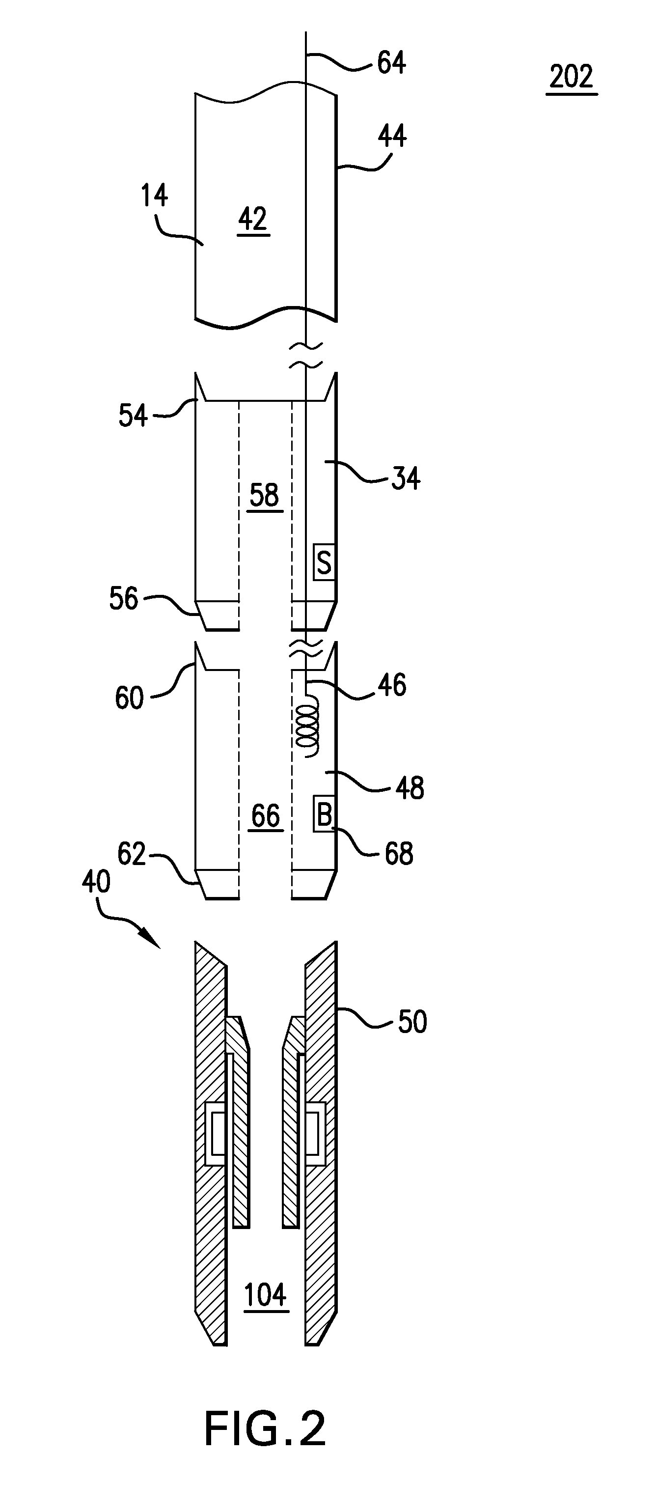
[0020]FIG. 1 shows an exemplary borehole 10 lined with a casing 12, and has a generally vertical section as well as a deviated or horizontal section 20. Alternatively, the borehole 10 is an open-type borehole where the formation wall 16 is not lined with casing 12. Inserted within the borehole 10 is a tubing 14, such as, but not limited to, coiled tubing. The tubing 14 includes any number of connected tubing pieces and is spoolable onto a reel (not shown) provided at a surface location 22. The tubing 14 includes any pipe or tubing that is conveyed from the surface location 22 within borehole 10, such as a completion string, logging string, drill string, or any other type of string or piping employed in a downhole operation. At a downhole end 24 of the tubing 14, a tool 18 may be carried for perfo...


PUM


Abstract

A friction reduction assembly for a downhole tubular. The friction reduction assembly includes an electrically activated friction reduction sub. The sub includes a flowbore fluidically connected to a flowbore of the tubular and remaining open for fluid flow therethrough during both activated and non-activated states of the friction reduction sub. A friction reducer responsive to an indication of lockup of the tubular, wherein friction between the tubular and surrounding casing or borehole is reduced in an electrically activated state of the friction reduction sub. A method of reducing friction in a downhole tubular is also included.

Description

BACKGROUND[0001]In the drilling and completion industry, the formation of boreholes for the purpose of production or injection of fluid is common The boreholes are used for exploration or extraction of natural resources such as hydrocarbons, oil, gas, water, and alternatively for CO2 sequestration. When coiled tubing is conveyed in highly deviated, long horizontal, lateral, up-dip, and even vertical boreholes, the tubing may reach a point of “lock-up” whereby the surface initiated snubbing force is insufficient to overcome the frictional forces between the coiled tubing and the casing or formation wall.[0002]There have been some attempts at overcoming such frictional forces by incorporating a valve to cyclically interrupt flow within the tubing to create pressure pulses. While such pressure pulses are capable of reducing frictional forces between the coiled tubing and the borehole environment, the valve typically temporarily blocks the flowbore of the tubing thereby disrupting flow ...

Claims


Application Information

Patent Timeline
IPC IPC(8): E21B23/14E21B34/06E21B17/20
CPCE21B23/14E21B34/066E21B17/20E21B23/04E21B41/0085E21B21/10
Inventor MACKENZIE, GORDON R.KELBIE, GRAEME K.
Owner BAKER HUGHES INC
Why Eureka
Try Eureka