Welding system with multiple user interface modules

a technology of user interface and user interface, applied in the field of welding systems, can solve problems such as operator confusion and outdated information

Active Publication Date: 2014-03-13
ILLINOIS TOOL WORKS INC
View PDF9 Cites 73 Cited by
  • Summary
  • Abstract
  • Description
  • Claims
  • Application Information

AI Technical Summary

Problems solved by technology

In some cases, a UI module may even display outdated information.
This disconnect of information within the system may result in conflicting settings, leading to operator confusion.

Method used


Image

  • Welding system with multiple user interface modules
  • Welding system with multiple user interface modules
  • Welding system with multiple user interface modules

Examples


Embodiment Construction

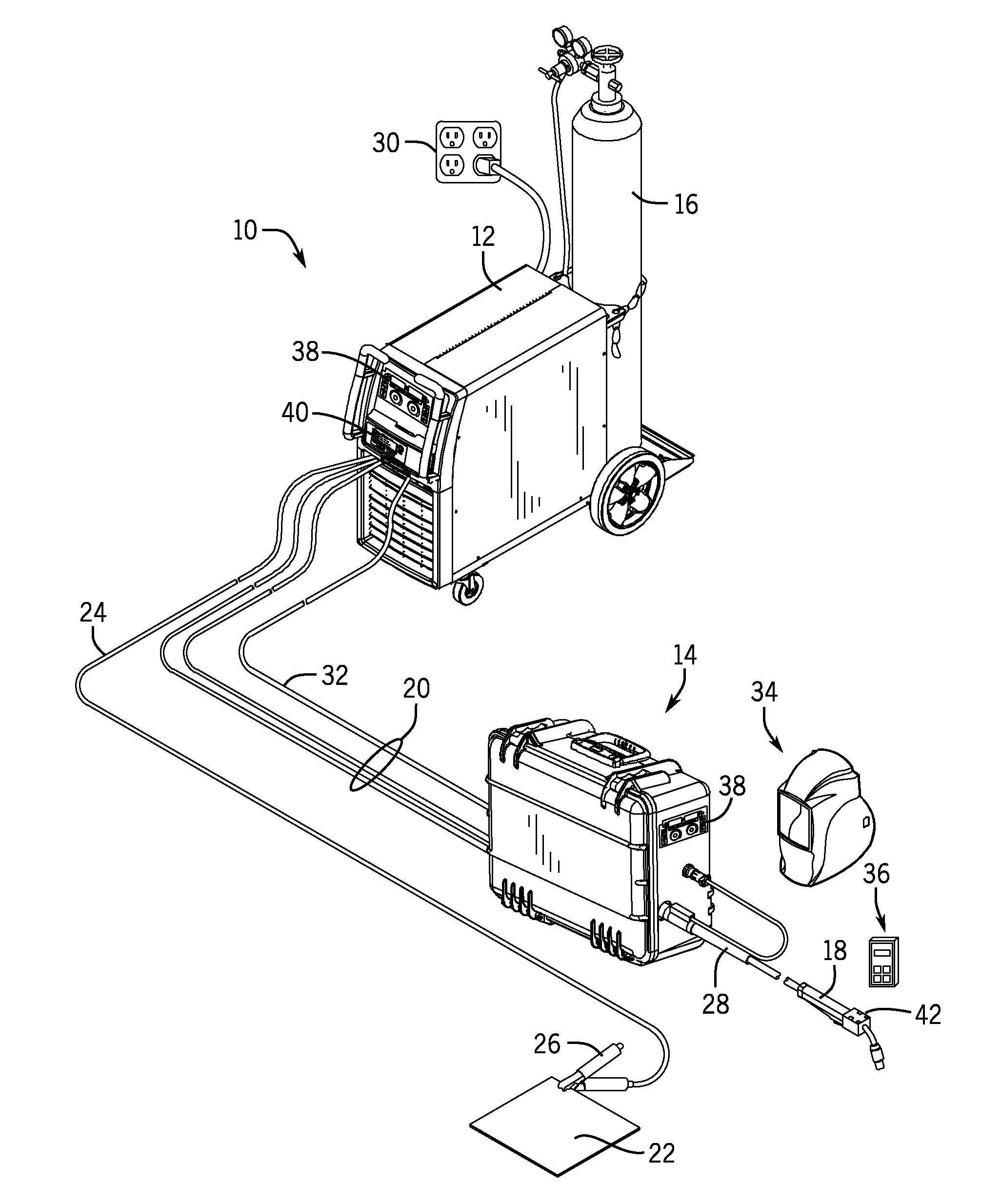
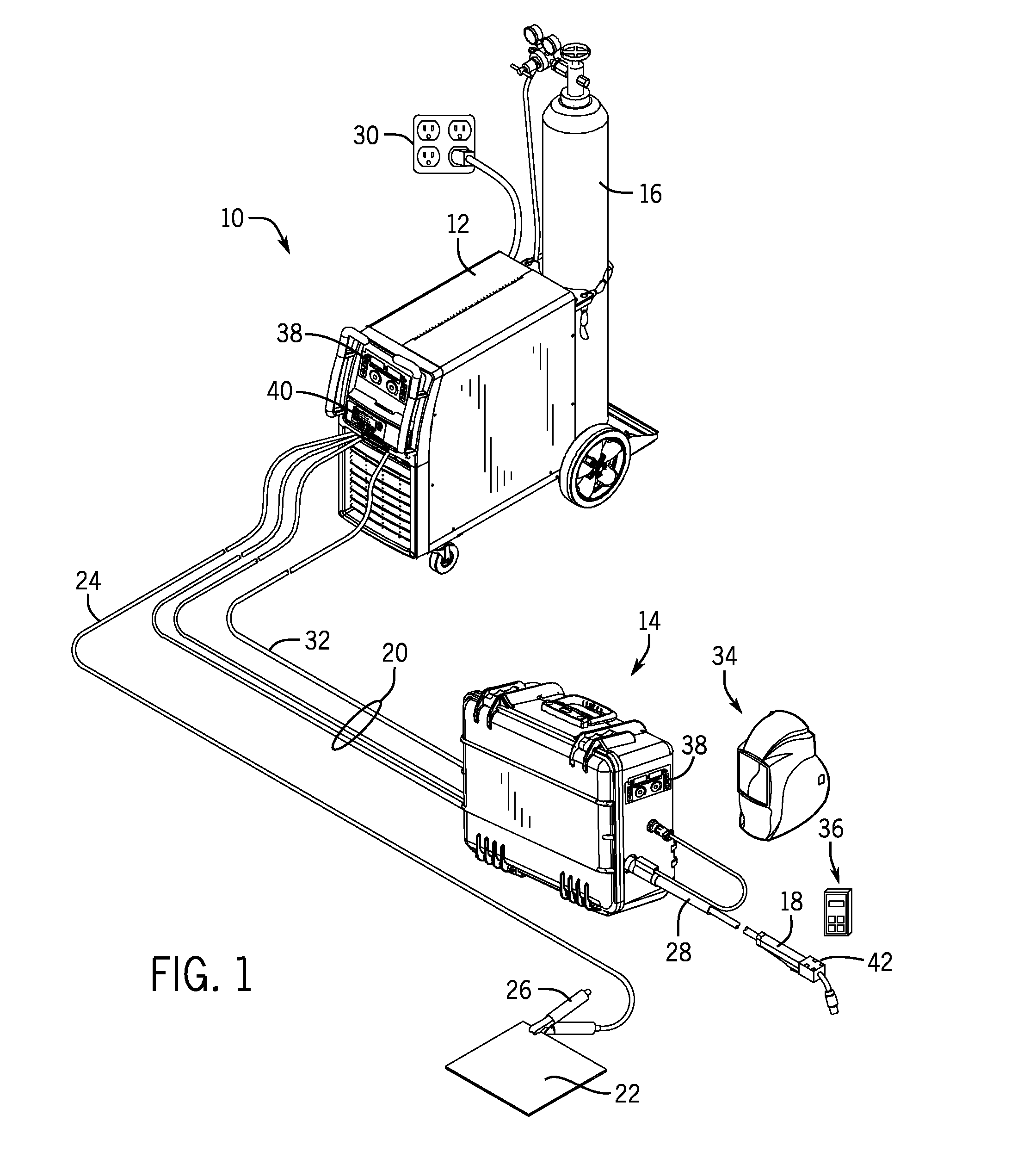
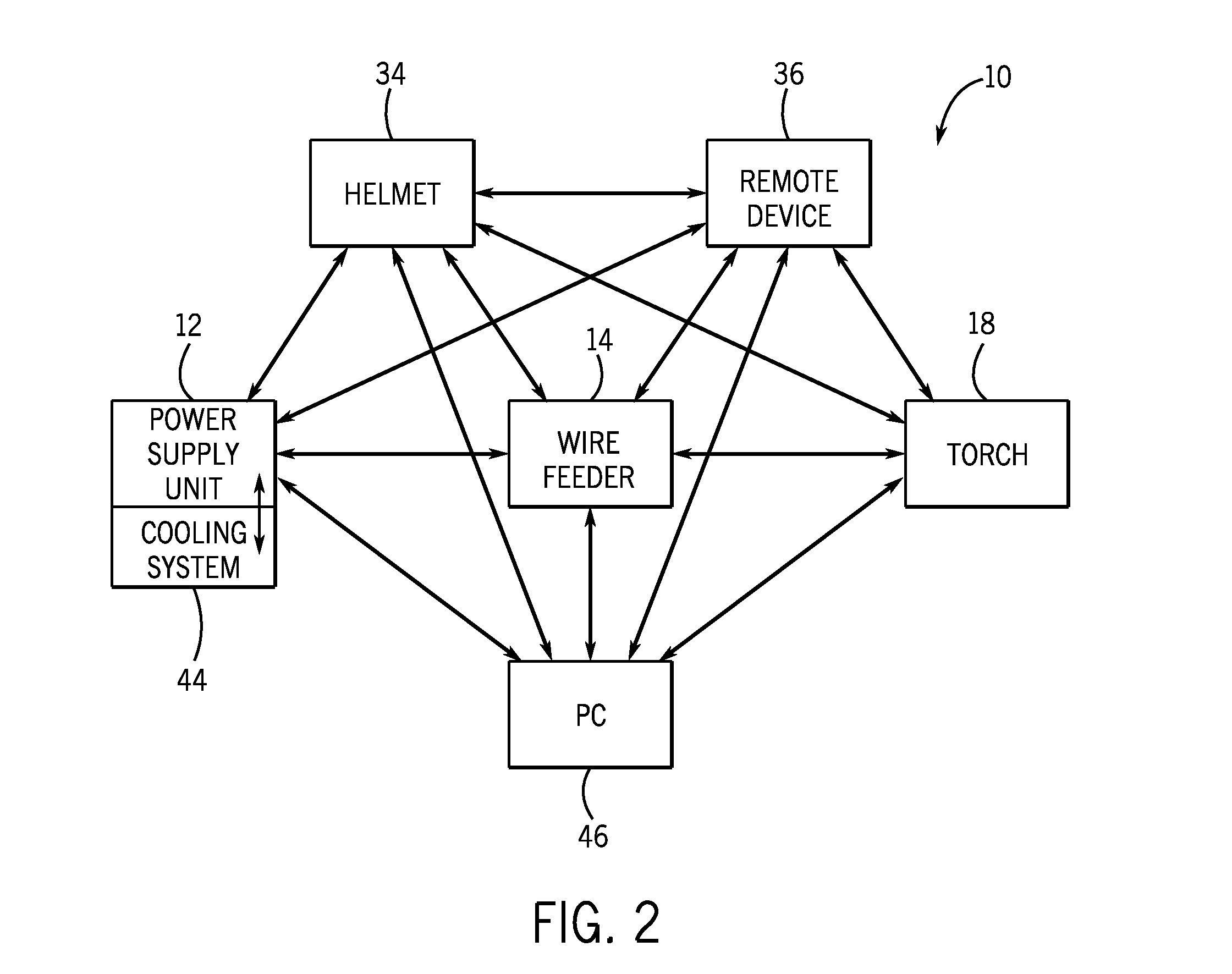
[0015]The embodiments described herein include improvements to welding system user interface modules. Such improvements may provide consistent data throughout all UI modules in the system, resulting in synchronized data (e.g., relating to operating parameters of the various welding system components, parameters relating to the welding process as a whole, and so forth) being provided to all of the components for improved welding system operability. The UI modules enable an operator to adjust and monitor the inputs and outputs of the welding system, which may be received from and distributed to multiple locations in a welding environment. The welding system may include multiple UI modules on various components within the system, such as a welding power source, a welding wire feeder, a welding torch, a welding helmet, a welding remote device (e.g., a pendant), a welding cooling system, a personal computer (PC), and so forth. The UI modules may be specifically designed for the specific ...


PUM

PropertyMeasurementUnit
timeaaaaaaaaaa
timeaaaaaaaaaa
timeaaaaaaaaaa

Abstract

A welding system user interface module includes a front panel comprising a first input device and a first display screen. The welding system user interface module also includes circuitry comprising a memory storing machine-readable instructions, a processor for executing the machine-readable instructions, and communication circuitry configured to receive UI data from the first input device or a second input device of a remote welding system user interface module, and to broadcast synchronized data to the first display screen and a second display screen of the remote welding system user interface module.

Description

CROSS-REFERENCE TO RELATED APPLICATION[0001]This application claims priority from and the benefit of U.S. Provisional Application Ser. No. 61 / 697,993, entitled “WELDING SYSTEM WITH MULTIPLE USER INTERFACE MODULES,” filed Sep. 7, 2012, which is hereby incorporated by reference in its entirety for all purposes.BACKGROUND[0002]The present invention relates generally to the field of welding systems, and more particularly to welding systems with multiple user interface modules that are synchronized.[0003]In typical welding systems, user interface (UI) modules may appear in many locations. However, the UI modules may each display different sets of information at the different locations. In some cases, a UI module may even display outdated information. This disconnect of information within the system may result in conflicting settings, leading to operator confusion.BRIEF DESCRIPTION[0004]In one embodiment, a welding system user interface module includes a front panel comprising a first inp...

Claims


Application Information

Patent Timeline
Patent Type & Authority Applications(United States)
IPC IPC(8): B23K9/095
CPCB23K9/0953B23K9/1087H04N21/41265G09G5/12H04N21/4126
Inventor MEHN, PETER DONALDNELSON, ANDREW DAVIDDECOSTER, RANDY ALAN
Owner ILLINOIS TOOL WORKS INC
Why Eureka
Try Eureka