Device for de-icing a turbomachine separator

a technology for turbomachines and separators, which is applied in the direction of gas turbine plants, pumps, non-positive displacement fluid engines, etc., can solve the problems of separators, ice to form on certain components, and separators that are sensitive to ice, and achieve the effect of efficient de-iceing the separator

Active Publication Date: 2014-03-13
SN DETUDE & DE CONSTR DE MOTEURS DAVIATION S N E C M A
View PDF14 Cites 1 Cited by
  • Summary
  • Abstract
  • Description
  • Claims
  • Application Information

AI Technical Summary

Benefits of technology

[0008]The invention seeks to remedy the disadvantages of the state of the art by proposing a device for de-icing a turbomachine separator which efficiently de-ices the separator, even if it is of small dimensions.

Problems solved by technology

Under “icing” conditions, turbojets draw in damp, cold air which will cause ice to form on certain components.
The components located at the front of the turbomachine, in particular the separator, are sensitive to ice and are not subject to, or are not sufficiently subject to, the effects of the centrifugal force which may protect them from a substantial accumulation of ice during a prolonged flight in icing atmospheric conditions.
However, separators are of increasingly small dimensions, such that it is increasingly difficult to insert ducts into the separator.
When this centring diameter has been installed in the separator the space left free for the air inlet duct is consequently small, such that the quantity of air from the high-pressure compressor which can be injected into the separator is limited.

Method used


Image

  • Device for de-icing a turbomachine separator
  • Device for de-icing a turbomachine separator
  • Device for de-icing a turbomachine separator

Examples


Embodiment Construction

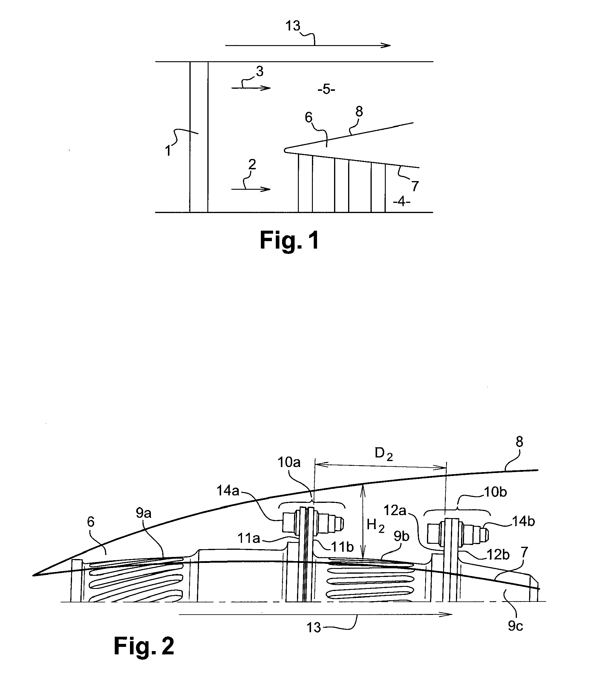
[0041]FIG. 1 represents a section view of a turbomachine in which the de-icing device according to the invention is preferably installed.

[0042]The turbomachine extends along a reference axis 13. In this document the term “axial” is used to designate a direction parallel to this reference axis, and the term “radial” is used to designate a direction perpendicular to this reference axis.

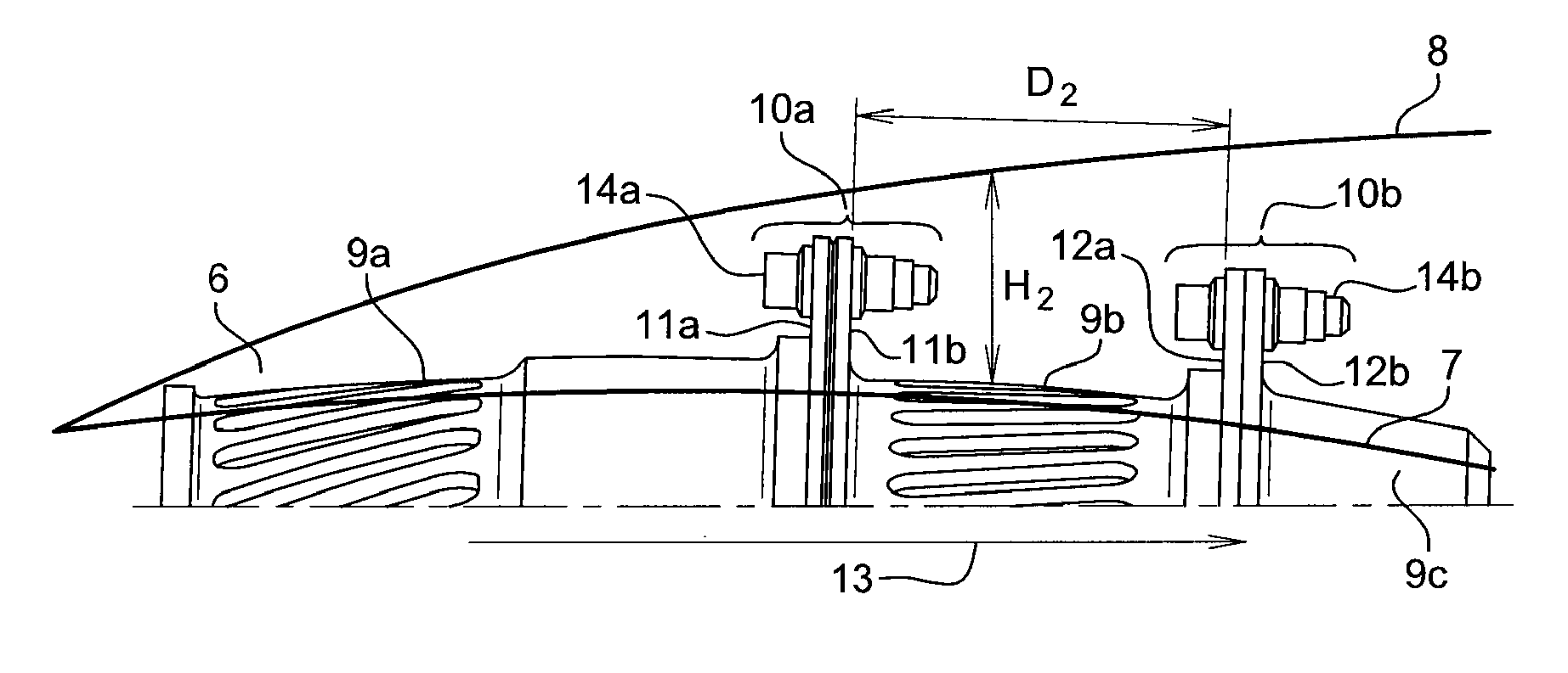
[0043]This turbomachine includes a first fan 1, behind which the air stream is separated into a primary stream 2 which flows in a primary flow path 4 and a secondary stream 3 which flows in a secondary flow path 5. Primary stream 2 and secondary stream 3 are separated by a separator 6 represented more accurately in FIG. 2. This separator 6 is formed by the intersection of an inner ferrule 7 and an outer ferrule 8. Inner ferrule 7 is formed by the assembly of rings 9a, 9b, 9c which are able to support rotor blades or flow straighteners. First ring 9a is assembled with second ring 9b using a first mountin...


PUM


Abstract

A turbomachine separator including a device for de-icing the turbomachine separator, and a distribution element, wherein the separator is formed by an inner ferrule and an outer ferrule, wherein the inner ferrule is fitted with a first mounting flange and a second mounting flange, the de-icing device including an internal air supply duct, able to inject air into the separator, wherein the internal supply duct is connected to an air inlet, wherein the air inlet forms a projection external to the de-icing device, allowing a flexible connection with a tube of the distribution element for conveying hot air, a first fastener constructed and arranged to be attached to the first mounting flange; and a second fastener constructed and arranged to be attached to the second mounting flange.

Description

TECHNICAL FIELD[0001]The present invention relates to a device for de-icing the front portions of a turbomachine, and more specifically the separator of a turbomachine. The invention also relates to a de-icing nozzle fitted with such a de-icing device, together with a turbomachine including such a de-icing device.STATE OF THE PRIOR ART[0002]During flight aircraft experience very diverse atmospheric conditions. These conditions differ according to the geographical locations, the seasons and also the flight altitude. Under “icing” conditions, turbojets draw in damp, cold air which will cause ice to form on certain components.[0003]Different parameters and different characteristics will restrict or increase the size of the formed ice mass. The components located at the front of the turbomachine, in particular the separator, are sensitive to ice and are not subject to, or are not sufficiently subject to, the effects of the centrifugal force which may protect them from a substantial accu...

Claims


Application Information

Patent Timeline
Patent Type & Authority Applications(United States)
IPC IPC(8): F01D25/02
CPCF01D25/02F02C7/047F05D2260/30
Inventor BELMONTE, OLIVIERBART, JACQUES RENE
Owner SN DETUDE & DE CONSTR DE MOTEURS DAVIATION S N E C M A
Why Eureka
Try Eureka