Swirl interruption seal teeth for seal assembly

a technology of seal teeth and swirl interruption, which is applied in the direction of machines/engines, mechanical equipment, liquid fuel engines, etc., can solve the problems of affecting the sealing effect of seal teeth, occupying additional axial space for conventional anti-swirl teeth, and inability to withstand swirling, etc., to achieve the effect of reducing steam for

Active Publication Date: 2014-03-13
GENERAL ELECTRIC CO
View PDF7 Cites 18 Cited by
  • Summary
  • Abstract
  • Description
  • Claims
  • Application Information

AI Technical Summary

Benefits of technology

[0005]Embodiments of this invention include a seal assembly for sealing between a rotating component and a stationary component in a turbomachine. The seal assembly includes a plurality of radially inwardly projecting, axially spaced teeth extending from the stationary component, where

Problems solved by technology

This causes the fluid to acquire the significant tangential velocity component, which can induce rotor instabilities in turbomachines.
As more and tighter seals are used in steam turbines, swirl-induced rotordynamic instability becomes mo

Method used


Image

  • Swirl interruption seal teeth for seal assembly
  • Swirl interruption seal teeth for seal assembly
  • Swirl interruption seal teeth for seal assembly

Examples


Embodiment Construction

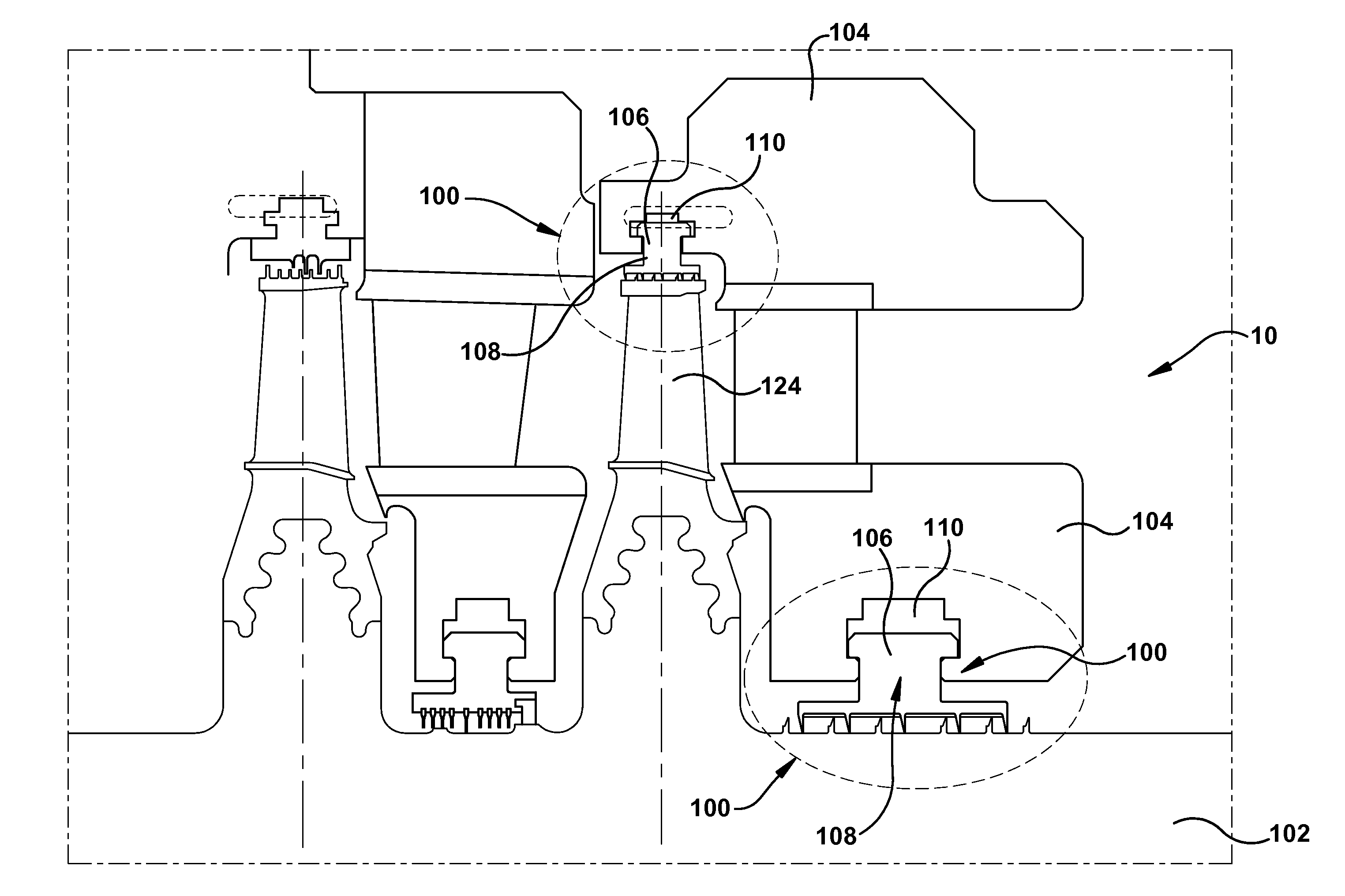
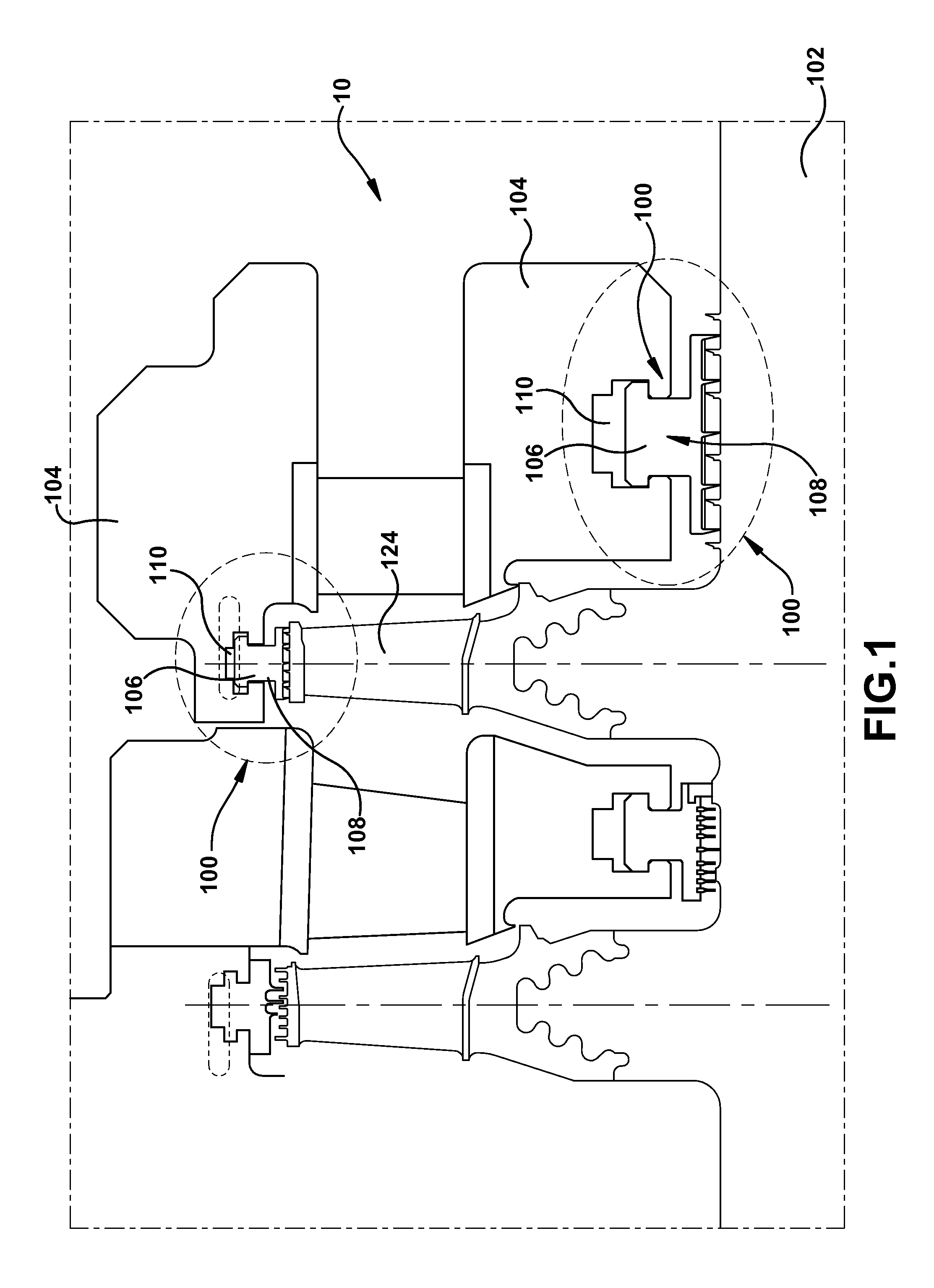
[0018]Turning to FIG. 1, a partial cross-sectional view of a machine 10 including a labyrinth seal 100 according to an embodiment of the invention is shown. Although FIGS. 1-4 are shown and discussed with respect to a steam turbine, it is understood that the teachings of the various embodiments of the invention may be similarly applied to other turbomachines and that a steam turbine is merely used as an example of one type of turbomachine to describe the aspects of the invention.

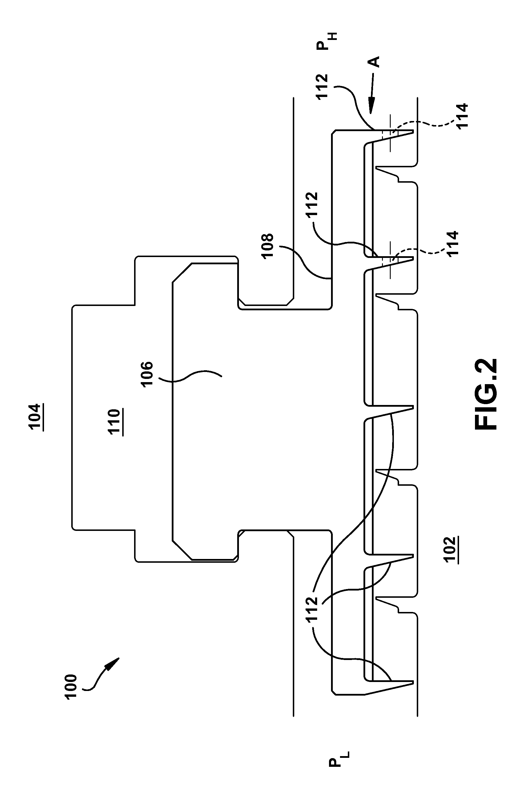
[0019]Turning to FIG. 1, turbomachine 10 includes a rotating element 102 and a stationary component 104. Stationary component 104 may substantially surround rotating element 102. Turbomachine 10 also includes at least one seal assembly 100 coupled to stationary component 104. As shown in FIG. 2, in one embodiment, seal assembly 100 may be coupled to stationary component 104 by fitting a mounting portion 106 of an arcuate packing ring 108 within a groove 110 of stationary component 102.

[0020]Seal assembly 100...


PUM


Abstract

A seal assembly for sealing between a rotating component and a stationary component in a turbomachine. The seal assembly includes a plurality of radially inwardly projecting, axially spaced teeth extending from the stationary component, wherein at least one of the plurality of teeth has at least one axially extending hole therethrough. Axial flow of an operating fluid through the holes acts as an air-curtain to interrupt swirl flow in a seal cavity, therefore reducing steam force that could act to destabilize rotordynamics.

Description

BACKGROUND OF THE INVENTION[0001]The present invention relates generally to a seal assembly, and more particularly to a seal assembly including at least one seal tooth having at least one hole to reduce swirl-induced rotordynamic instability.[0002]In rotary machines such as turbines, seals are provided between rotating and stationary components. For example, in steam turbines, it is customary to provide a plurality of arcuate packing ring segments to form an annular labyrinth seal between the stationary and rotating components. Typically, the arcuate packing ring segments (typically, four to six per annular seal) are disposed in an annular groove in the stationary component concentric to the axis of rotation of the machine and hence concentric to the sealing surface of the rotating component. Each arcuate seal segment carries an arcuate seal face in opposition to the sealing surface of the rotating component. In labyrinth type seals, a plurality of axially spaced, circumferentially ...

Claims


Application Information

Patent Timeline
IPC IPC(8): F01D11/02
CPCF01D11/02F01D11/08F05D2220/32F05D2240/55F05D2250/191F05D2260/14F16J15/4472
Inventor ZHENG, XIAOQINGBROWN, DANIEL MARKJEWETT, JASON WINFREDWILLETT, JR., FRED THOMAS
Owner GENERAL ELECTRIC CO
Why Eureka
Try Eureka