Apparatus and method for energy distribution in a medical electrode

a technology of medical electrodes and apparatus, applied in the field of multi-functional medical electrodes, can solve the problems of time-consuming and costly process of fanning out individual conductor strands

Active Publication Date: 2014-03-13
KPR U S LLC
View PDF3 Cites 12 Cited by
  • Summary
  • Abstract
  • Description
  • Claims
  • Application Information

AI Technical Summary

Benefits of technology

[0006]In one aspect of the invention, a medical electrode includes an electrode member having a top face and a bottom face, an electrical conductor having an unfanned, unsheathed end portion for conducting energy between the electrode member and a medical device, an energy blocking layer disposed between the electrode member and the unfanned, unsheathed end portion of the electrical cond

Problems solved by technology

One of the difficulties in manufacturing medical electrodes has been attachment of the electrical conductor which is generally in the form o

Method used


Image

  • Apparatus and method for energy distribution in a medical electrode
  • Apparatus and method for energy distribution in a medical electrode
  • Apparatus and method for energy distribution in a medical electrode

Examples


Embodiment Construction

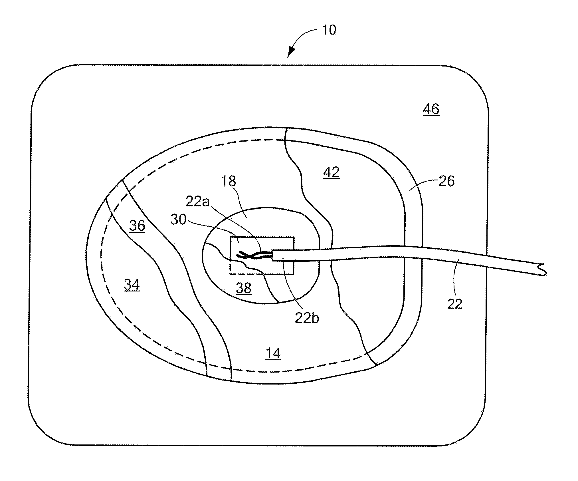
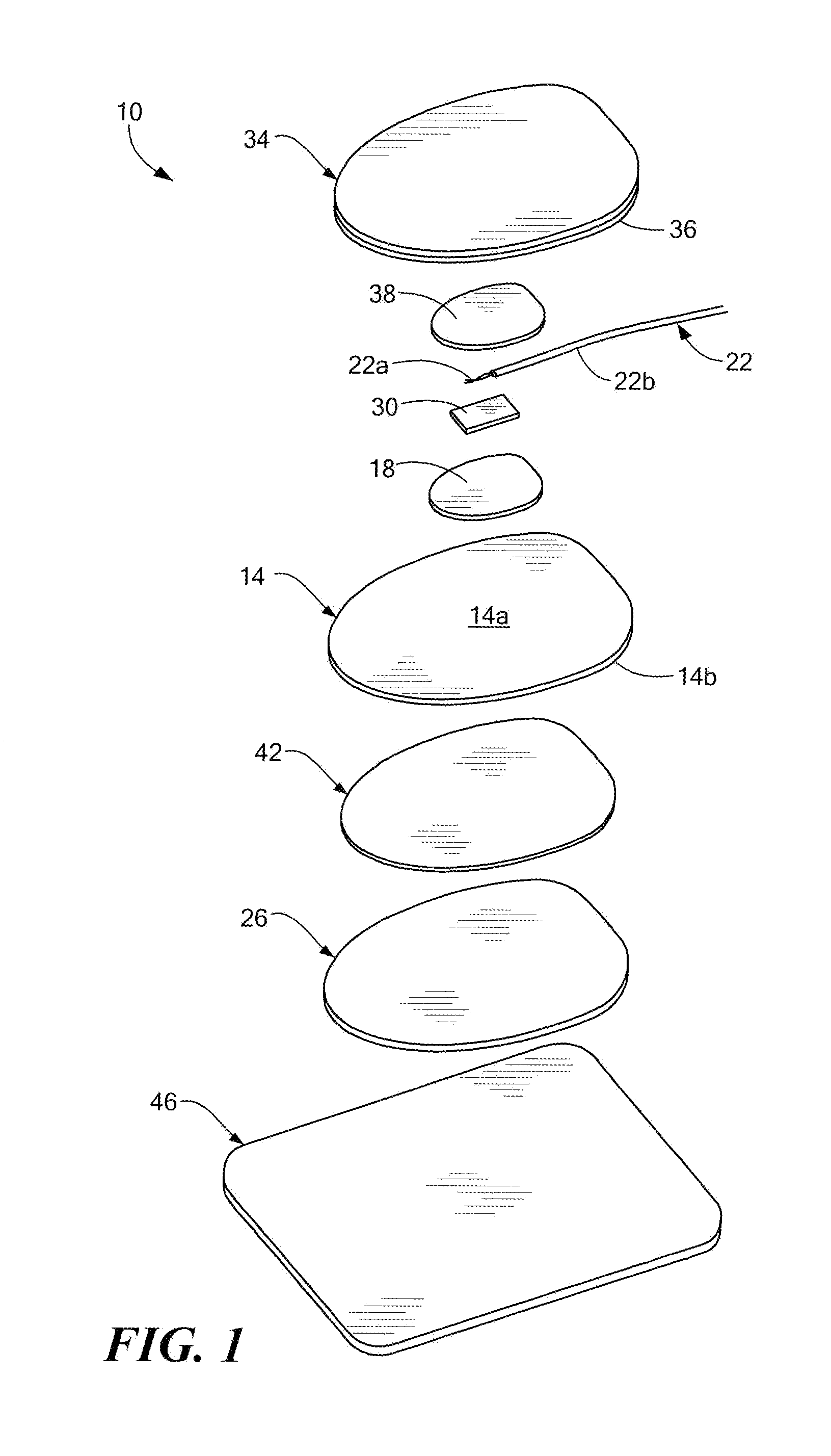
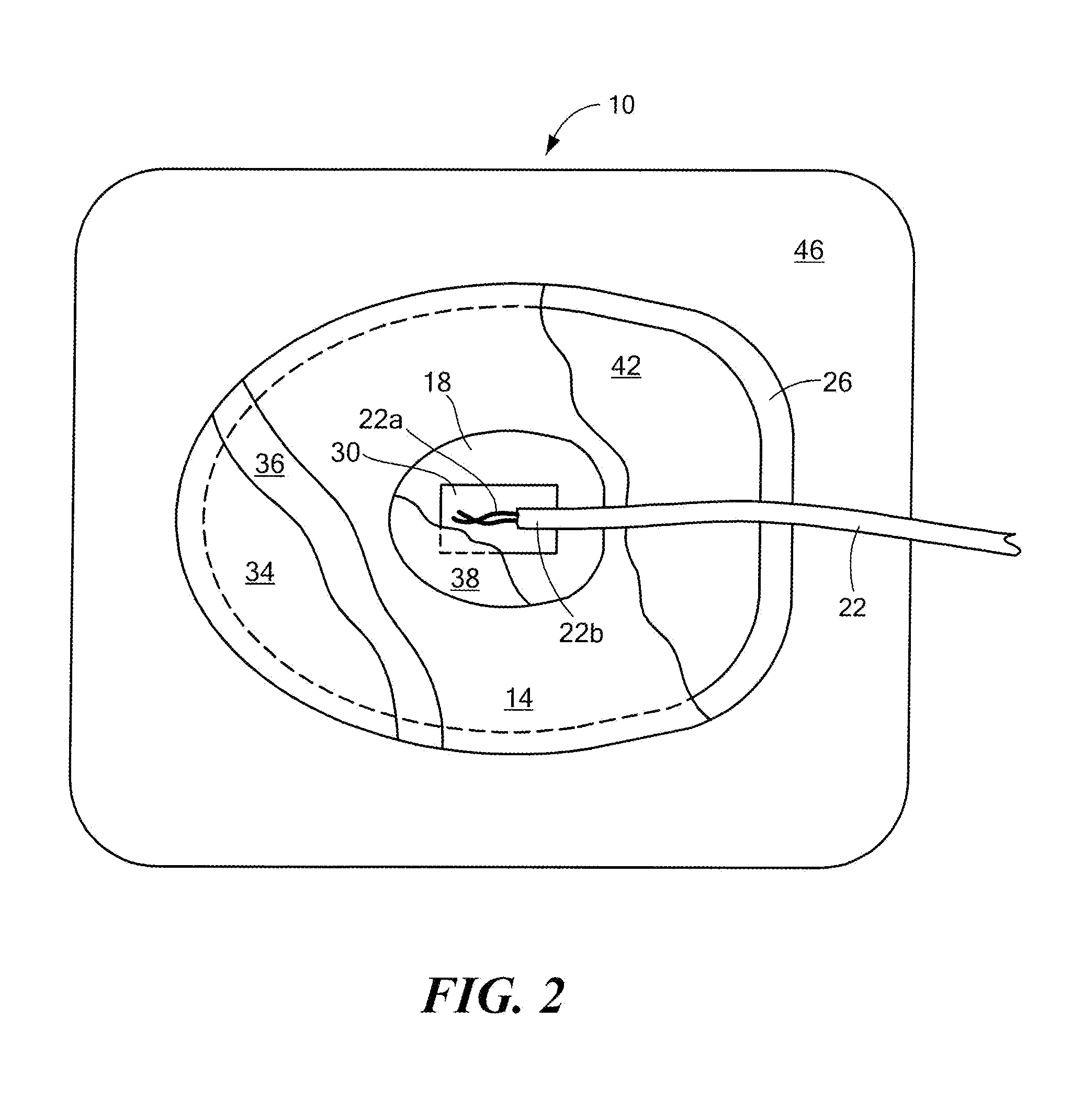
[0018]Referring to the exploded view of FIG. 1, a medical electrode 10 includes a conductive electrode member 14 having a top face 14a and a bottom face 14b, an electrical conductor 22 having an unfanned, unsheathed end portion 22a for conducting energy between the electrode member and a medical device (FIG. 6), and a patient contacting layer 26 secured to at least a portion of the bottom face of the electrode member. By providing the electrode 10 with an electrical conductor having an unfanned end portion 22a, the manufacture of the electrode is suitable for automation, and therefore, simplified as compared to conventional medical electrodes in which the individual strands of the electrical conductor are manually fanned out.

[0019]An energy blocking layer 30 is disposed between the unfanned, unsheathed conductor end portion 22a and the top face 14a of the electrode member 14. The energy blocking layer 30 prevents the immediate transfer of energy from the conductor 22 to the electrod...


PUM

PropertyMeasurementUnit
Electrical conductivityaaaaaaaaaa
Currentaaaaaaaaaa
Electrical conductoraaaaaaaaaa

Abstract

A medical electrode includes an electrode member having a top face and a bottom face, an electrical conductor having an unfanned, unsheathed end portion for conducting energy between the electrode member and a medical device, and a patient contacting layer secured to at least a portion of the bottom face of the electrode member. An energy blocking layer is disposed between the unfanned conductor end portion and the electrode member to prevent immediate transfer of energy to the electrode member. A current distributing structure is described to conduct and distribute energy to the electrode member.

Description

RELATED APPLICATIONS[0001]This application claims priority under 35 U.S.C. 119(e) to U.S. application Ser. No. 61 / 700,334 filed on Sep. 13, 2012 entitled APPARATUS AND METHOD FOR ENERGY DISTRIBUTION INA MEDICAL ELECTRODE, which is incorporated herein by reference in its entirety for all purposes.FIELD OF THE INVENTION[0002]This invention relates generally to medical electrodes and, more particularly, to a multifunction medical electrode with improved manufacturability and reduced cost.BACKGROUND OF THE INVENTION[0003]Conventional medical electrodes generally include a conductive electrode member and an electrical conductor that provides an electrical interface between the electrode and various types of medical equipment, such as monitoring equipment and stimulating equipment. Illustrative monitoring equipment includes electrocardiograph (ECG) monitors and illustrative stimulating equipment includes transcutaneous stimulation equipment and defibrillators.[0004]Some known electrodes, ...

Claims


Application Information

Patent Timeline
IPC IPC(8): A61B5/04
CPCA61B5/04A61B2562/125A61N1/048A61N1/0492A61N1/046Y10T29/49117A61B2562/0215A61B5/259A61N1/368A61B5/25A61B5/263A61B5/265A61B2562/0209A61B5/24
Inventor HYATT, CHRISTOPHER J.COGGINS, SCOTT R.
Owner KPR U S LLC
Why Eureka
Try Eureka