Washing machine

a washing machine and washing machine technology, applied in the field of washing machines, can solve the problems of uneven distribution of the laundry, limited movement of the washing machine, and vibration of the conventional washing machine,

Active Publication Date: 2014-03-20
SAMSUNG ELECTRONICS CO LTD
View PDF3 Cites 8 Cited by
  • Summary
  • Abstract
  • Description
  • Claims
  • Application Information

AI Technical Summary

Benefits of technology

[0033]According to the above description, two kinds of ball balancing groups are used, and accordingly the ball accommodation portion has at least two steps. Therefore, a compact balancing device may be realized. In addition, since the ratio of the diameter of the small-diameter balancing balls to the diameter of the large-diameter balancing balls is between about 0.25 and about 0.9, the area of the portion of the large-diameter balancing ball stuck in the concave portion accommodating the small-diameter balancing balls decreases, and therefore, the large-diameter balancing balls may move easily in a circumferential direction.

Problems solved by technology

The conventional washing machine is subjected to vibration when the spin basket having laundry accommodated therein rotates to perform drying operation.
This vibration mainly results from uneven distribution of the laundry accommodated in the spin basket.
The balancing balls are submerged in the viscous fluid and thus movement thereof is limited to an extent.
Thereby, self-excited vibration of the balancing balls revolving in the accommodation chamber may be restricted.
If the horizontal vibration of the spin basket is large, the outer tub may collide with the outer casing.
This may waste energy and time.
Thereby, unbalanced positioning of the balancing balls before start of the drying operation of the washing machine is resolved.
Thereby, movement of the balancing balls may be restricted by the viscous resistance of the viscous fluid, and thus it may be difficult to accommodate the balancing balls in the recessed accommodation portion.
However, this control may take energy and time.

Method used


Image

  • Washing machine
  • Washing machine
  • Washing machine

Examples


Embodiment Construction

[0046]Reference will now be made in detail to the embodiments of the present disclosure.

[0047]Hereinafter, embodiment of the present disclosure will be described in detail with reference to the accompanying drawings, wherein like reference numerals refer to like elements throughout. The embodiments are simply illustrative and are not intended to limit the present disclosure,

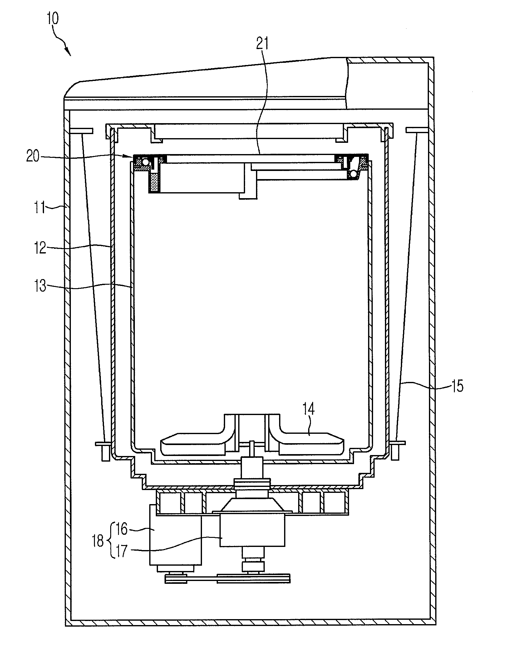
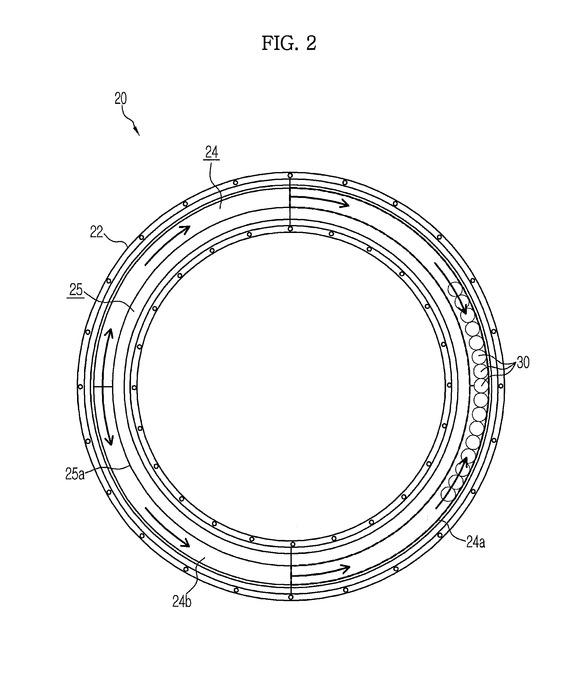
[0048]FIG. 1 is a longitudinal cross-sectional view showing a bell-shaped electric washing machine (hereinafter, referred to as a washing machine). As shown in FIG. 1, the washing machine 10 includes an outer casing 11, an outer tub 12 (also referred to as a water tub), a spin basket 13 (also referred to as a washing tub), and a balancing device 20 (also referred to as a ball balancer).

[0049]The outer casing 11 is formed in the shape of an approximately rectangular box having a bottom. The outer tub 12 is elastically supported through a suspension 15 in the outer casing 11. That is, the suspension 15 connects the...


PUM


Abstract

A washing machine provided with a balancing device which may suppress variation in horizontal vibration of a spin basket without performing control operation. The balancing device includes a ring-shaped casing installed to be concentric with the spin basket, and a plurality of the balancing balls and a viscous fluid. A ring-shaped ball accommodation portion, a fluid accommodation portion provided at a lower inner side of the ball accommodation portion in a radial direction of the ball accommodation portion, and a communication channel are formed in the casing. The fluid accommodation portion is provided at a portion of the casing along a circumferential direction of the casing. A bottom surface of the ball accommodation portion is inclined downward such that the balancing balls gather at the opposite position facing the fluid accommodation portion when rotation of the spin basket is stopped.

Description

CROSS-REFERENCE TO RELATED APPLICATIONS[0001]This application claims the benefit of Japanese Patent Applications Nos. 2012-209179 and 2012-202282, both filed on Sep. 14, 2012 in the Japanese Patent Office, and Korean Patent Application No. 10-2013-0064893, filed on June 5, 2013 in the Korean Intellectual Property Office, the disclosures of which are incorporated herein by reference.BACKGROUND[0002]1. Field[0003]Embodiments of the present disclosure relate to a washing machine having an outer tub, a spin basket rotatably installed in the outer tub, and a balancing device mounted to the spin basket.[0004]2. Description of the Related Art[0005]Conventionally, a washing machine having an outer tub and a spin basket rotatably installed in the outer tub to perform washing, rinsing and drying of laundry such as clothing accommodated in the spin basket has been known.[0006]The conventional washing machine is subjected to vibration when the spin basket having laundry accommodated therein rot...

Claims


Application Information

Patent Timeline
Patent Type & Authority Applications(United States)
IPC IPC(8): D06F37/24
CPCD06F37/245D06F21/06
Inventor ATSUSHI, OHYAGIIZUMI, IKEDA
Owner SAMSUNG ELECTRONICS CO LTD
Why Eureka
Try Eureka