
In SItu Membrane Monitoring

a technology of in situ membrane and monitoring device, which is applied in the direction of membranes, instruments, material impedance, etc., can solve the problems of significant negative impact of reduction of membrane rejection characteristics, reducing salt rejection, and reducing membrane rejection characteristics. to achieve the effect of reducing precision

Inactive Publication Date: 2014-03-20
INPHAZE AUSTRALIA PTY LTD
View PDF2 Cites 6 Cited by
  • Summary
  • Abstract
  • Description
  • Claims
  • Application Information

AI Technical Summary

Benefits of technology

Enables continuous and early detection of fouling, maintaining membrane performance by preventing flux reduction and salt rejection decline, thus improving the operational efficiency and quality of permeate water in membrane separation systems.

Problems solved by technology

Fouling leads to a reduced permeate flux and can also lead to a decrease in the rejection characteristics of the membrane.
Any reduction in the rejection characteristics has a significant negative impact, particularly on the performance of so called “Reverse Osmosis” membranes for removing salt from sea water or brackish feed water.
In particular, fouling in such membranes will give rise to reduced salt rejection and hence lower quality (higher salinity) permeate fluxes.

Method used


Image

  • In SItu Membrane Monitoring
  • In SItu Membrane Monitoring
  • In SItu Membrane Monitoring

Examples


Embodiment Construction

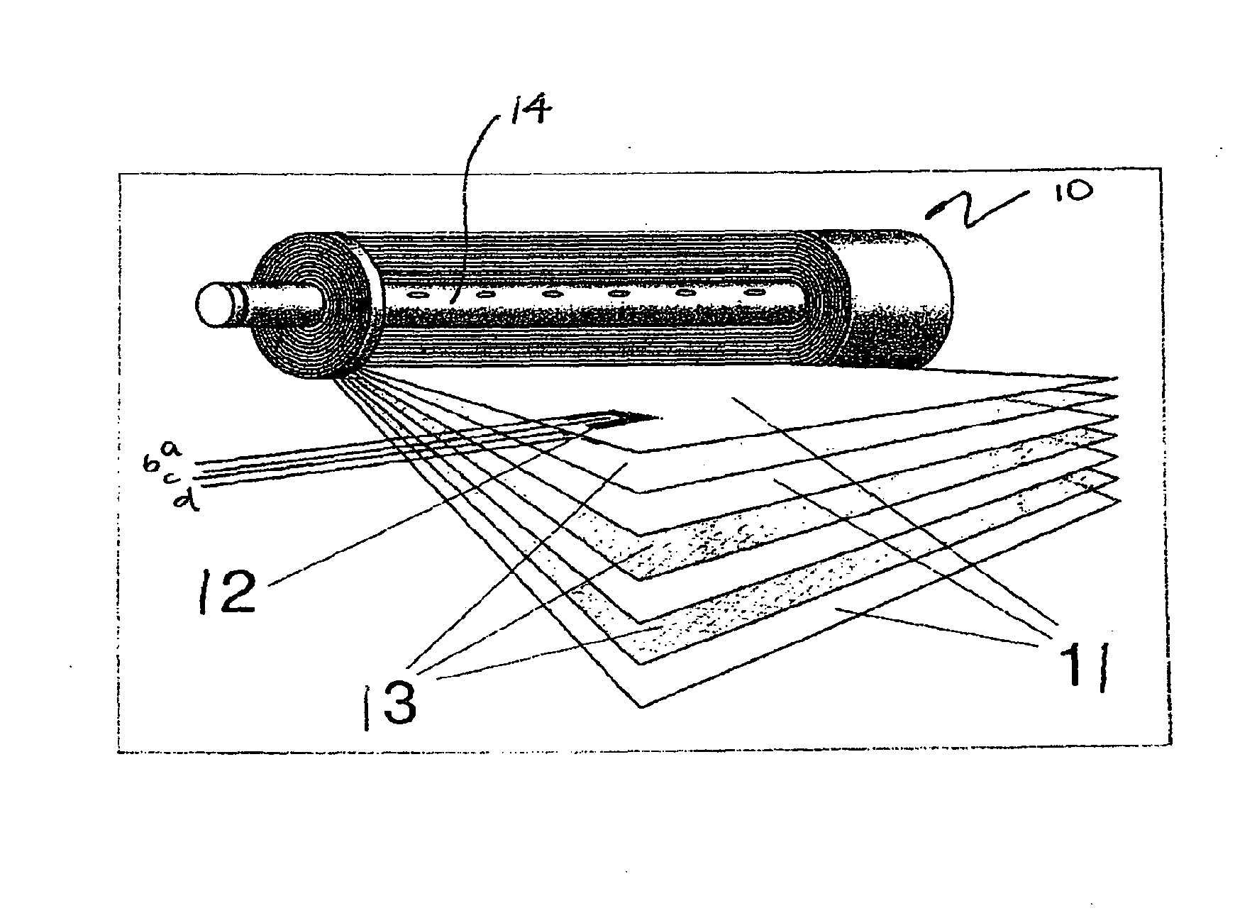
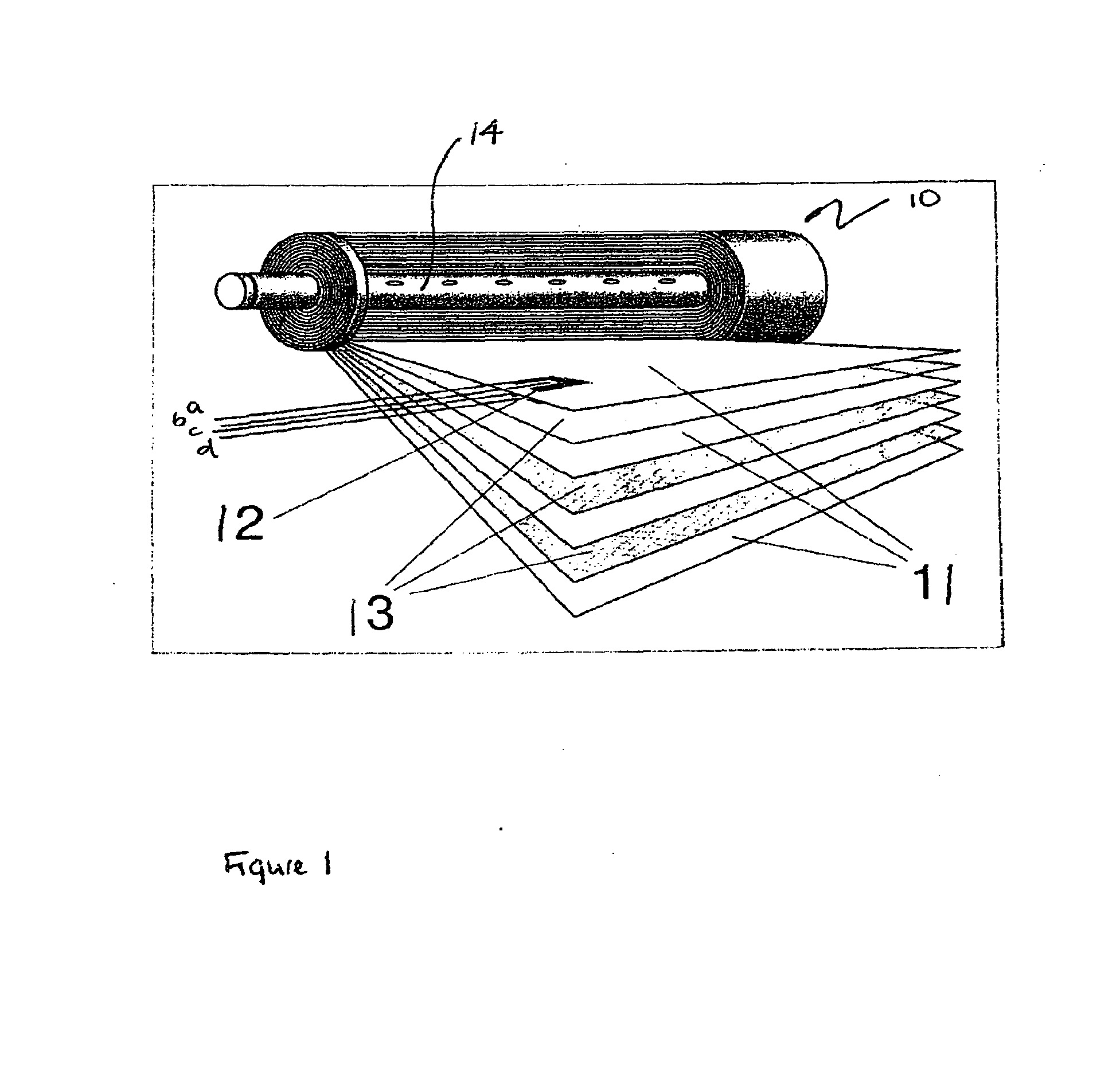
[0052]Referring to the drawings, FIG. 1 shows a “spiral wound” membrane separation module 10 including electrodes 12. In the drawing part of the module is shown “unwound” showing a cut-away view of the membranes 11 and spacers 13, as well as the electrodes 12 located within the spacers.

[0053]In operation, feed fluid is driven under pressure on one side of each membrane 11 whilst the permeate is collected from the other side. The permeate moves radially towards the centre of the module 10 along the spacer 13 between adjacent membranes 11 to a central permeate collection tube 14. The feed fluid moves between adjacent membranes, longitudinally along the module. This also provides a so called “crossflow” that assists in preventing fouling of the membranes. The spacers 13 are usually constructed from about 1 mm thick polymer threads made into a fabric. The spacers 13 provide a space between adjacent membranes in both the feed side and permeate side.

[0054]FIG. 1 shows a system with two pa...


PUM

PropertyMeasurementUnit
diameteraaaaaaaaaa
sizeaaaaaaaaaa
areaaaaaaaaaaa

Abstract

A method for in situ monitoring of a membrane of a membrane separation system comprises measuring a complex impedance of the membrane at a plurality of frequencies to provide an indication of the electrical conduction and electrical polarization properties of the membrane. The membrane based separation system for removing or reducing the concentration of materials carried in a fluid including a separation membrane has a first pair of electrodes separated by the membrane and arranged for measurement of the complex impedance of the membrane at a plurality of frequencies to provide the indication of the membrane properties. There may also be a second pair of electrodes separated by the membrane for injecting the stimulus current such that the injecting and monitoring functions are separated.

Description

CROSS-REFERENCE TO RELATED APPLICATIONS[0001]This application is a divisional of a U.S. Patent Application entitled “In Situ Membrane Monitoring”, assigned Ser. No. 12 / 677,890, filed Mar. 12, 2010, which claimed priority to PCT Application No. PCT / AU08 / 001356, international filing date 11 Sep. 2008, which claimed priority to Australian Application No. 2007905045, filed on 14 Sep. 2007.FIELD OF THE INVENTION[0002]This invention relates to a device and method for making impedance spectroscopy measurements of membranes in membrane separation modulesBACKGROUND OF THE INVENTION[0003]Membrane separation systems are used for a wide variety of processes in which it is desired to remove or reduce the concentration of certain materials in a fluid. In particular they are used to purify waste water effluents from industrial and domestic water use. They are also increasingly being used for producing fresh water from sea water or brackish water supplies by removing the salt, and other contaminant...

Claims


Application Information

Patent Timeline
Patent Type & Authority Applications(United States)
IPC IPC(8): G01N27/12G01N7/10
CPCG01N7/10G01N27/12B01D61/025B01D61/12B01D63/103B01D65/104B01D2313/345G01N27/026G01N17/008G01N27/02
Inventor COSTER, HANS GERARD LEONARDCHILCOTT, TERRY CALVIN
Owner INPHAZE AUSTRALIA PTY LTD
Learn More