Liquid droplet ejecting apparatus

a technology of ejecting apparatus and liquid droplets, which is applied in printing and other directions, can solve the problems of clogging of nozzles, air bubbles may be produced, and droplets of ink may not be ejected, and achieve the effect of restoring the ejection performance of recording heads, without increasing the number of components and assembly steps and the cos

Active Publication Date: 2008-09-09
BROTHER KOGYO KK
View PDF40 Cites 13 Cited by
  • Summary
  • Abstract
  • Description
  • Claims
  • Application Information

AI Technical Summary

Benefits of technology

[0029]The present invention has been developed in view of the above-described situations, and it is an object of the invention to provide a liquid droplet ejecting apparatus having a purging mechanism that restores an ejection performance of a recording head by pressurizing a liquid in a temporary storing chamber to pressure-feed the liquid toward the nozzle, without increasing the numbers of components and assembly steps and the cost.

Problems solved by technology

Further, the air bubbles may be produced when the ink in the sub tank is shook or moved during the inkjet recording apparatus is transferred.
The highly viscous ink and the bubbles in the recording head clog the nozzles to deteriorate the ink ejection performance of the recording head, namely, droplets of the ink may not be ejected as desired in forming an image.
Such a foreign material may also cause the clogging of the nozzles.
Hence, the fresh ink is necessarily sucked to an amount corresponding to an inner volume of the cap, leading to a large volume of the ink wasted.
However, the inkjet recording apparatus disclosed in the first publication has a drawback that even when the pump is reduced in size, employment of the pump and a driving device for the pump is essential, making the structure of the apparatus complex, and an overall size of the apparatus large.
However, the inkjet recording apparatus disclosed in the second publication where the lid is manually closed by a user to apply a pressure to the air and in turn the ink in the ink cartridge, has a drawback that a speed at which the lid is closed fluctuates, thereby causing a variation in the applied pressure, and making it difficult to stably implement the purging operation.
However, a solenoid valve is generally large in size and high in price, which works against the downsizing and cost reduction of the inkjet recording apparatus.
Thus, in practice, a solenoid valve can not be used in view of the cost effectiveness.
The pump mechanism for restoring the ink ejection performance is disadvantage in the following.
The O-ring disposed between the cylinder and the plunger to allow the relative sliding movement in friction between the plunger and the cylinder may be damaged by wear or secular change or for other reasons.
This means that the bottom of the cylinder keeps closing the ink supply port, inhibiting the supply of the ink, whether by the pressure-feeding or not, into the recording head.
Further, since the technique of the third publication requires the O-ring and the vertically displaceable cylinder, the number of components and accordingly the cost of the recording apparatus are large, and also the number of production steps can not be reduced.
Thus, the pressure loss is large, making the purging operation inefficient.
In addition, by the compression of the air, the ink may flow in the reverse direction also, that is, the ink may flow back toward an ink supply source as well as toward the recording head, thereby further lowering the efficiency of the purging.
In the arrangement where the air is compressed first, the speed of the ink flow rises relatively slowly, due to the large pressure loss.
Hence, before the speed reaches the sufficient level for purging, a large amount of the ink flows out of the recording head, leading to much waste of ink.
Hence, an overall size of the apparatus and the cost are increased, while the load imposed on the purging mechanism is high.
However, this arrangement may generate ink flow in the reverse direction toward the ink supply source when the pressure applied to change the inner volume is eliminated, thereby lowering the efficiency.
This troubles the user very much, deteriorating the user-friendliness.
All the above-described drawbacks are seen not only in the inkjet recording apparatus, but also in various kinds of liquid droplet ejecting apparatuses where a liquid stored in a sub tank is supplied to an ejecting head having a nozzle from which the liquid is ejected in the form of droplets.

Method used


Image

  • Liquid droplet ejecting apparatus
  • Liquid droplet ejecting apparatus
  • Liquid droplet ejecting apparatus

Examples


first embodiment

[0106]Referring to FIGS. 1 to 9, there will be described an inkjet recording apparatus according to a first embodiment of the invention, as used in a multifunction apparatus having a plurality of functions such as print function, scan function, copy function, and facsimile function.

1>

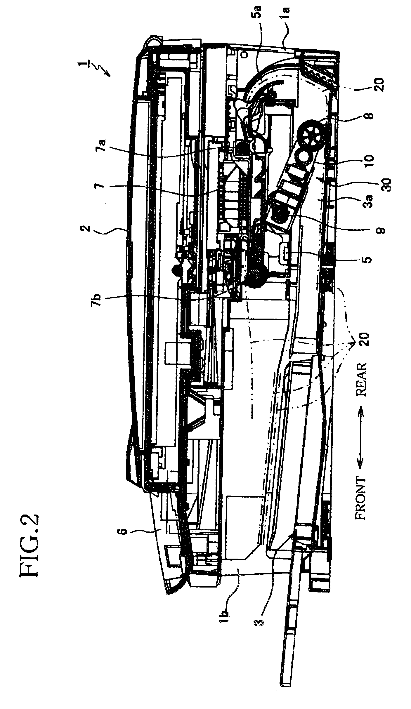
[0107]In FIGS. 1 and 2, reference numeral 1 generally denotes a multifunction apparatus 1 according to the first embodiment, which has a casing 1a, and a scanner 2 disposed on an upper side of the casing 1a. In an upper portion of an internal space of the casing 1, an inkjet recording apparatus 7 that performs recording, namely, forming an image on a recording medium 20 in an operation of any relevant one of the various functions. In a lower portion of the internal space of the casing 1a, a medium feeder 30 is disposed.

[0108]In a rear portion of the space inside the casing 1a and above the medium feeder 30, a box-shaped metal frame 5 is disposed. The frame 5 has a substantially rectangular shape extendi...

second embodiment

[0181]There will be now described an inkjet recording apparatus according to a second embodiment of the invention, by referring to FIG. 10.

[0182]In the first embodiment, as described with respect to the recording processing shown in FIG. 8, when the purging operation is performed at the relevant timing, once, the presser roller 14 is lowered down to the predetermined pressing position, the presser roller is held at this pressing position until all the four sub tanks 31, 41, 51, 61 have passed under the presser roller 14 and thus the purging has been performed for all the sub tanks 31, 41, 51, 61, and thereafter the presser roller 14 is returned to the retracted position.

[0183]On the other hand, according to the second embodiment, it is selectable whether the presser roller 14 is to be lowered to the pressing position, for each of the sub tanks 31, 41, 51, 61. Except this feature, the second embodiment is identical with the first embodiment, and thus the corresponding elements or par...

third embodiment

[0198]In the first embodiment, as described above with respect to the recording processing illustrated in FIG. 8, when the purging is performed at the timing for that operation, the velocity of the carriage 4 is selectively set at a or b to adjust the amount of the ink to be discharged.

[0199]In the present embodiment, on the other hand, the pressure applied upon the positive-pressure purging, and accordingly the amount of the discharged ink is made adjustable, by selecting whether the presser roller 14 brought into contact with the elastic support member of the sub tank is thereafter held in the contacting state until the presser roller 14 naturally separates from the elastic support member as the sub tank holding the head unit 11 laterally moves, or the presser roller 14 is retracted to the retracted position before the presser roller 14 naturally separates from the elastic support member as the sub tank laterally moves and while the elastic support member 35 is being elastically d...


PUM


Abstract

There is disclosed a liquid droplet ejecting apparatus including: a tank storing a liquid; a nozzle from which the liquid is ejected in the form of a droplet; a first pressure-feed portion which is disposed between the tank and the nozzle, and pressure-feeds the liquid as supplied from the tank, to eject the liquid droplet from the nozzle; a second pressure-feed portion which has an inner volume larger than that of the first pressure-feed portion, and is disposed between the tank and the first pressure-feed portion, the second pressure-feed portion pressure-feeding the liquid as supplied from the tank to the nozzle via the first pressure-feed portion, to eject the liquid from the nozzle in an amount larger than an amount of the liquid ejected by the first pressure-feed portion as the liquid droplet; and the second pressure-feed portion including: a pressure chamber; a pressurizing member that pressurizes the liquid in the pressure chamber by decreasing an inner volume of the pressure chamber; and a liquid communication passage which holds the tank and the nozzle in communication with each other via the pressure chamber, and which includes a flow resistance generator which is disposed in at least one of a portion of the liquid communication passage between the tank and the pressure chamber, and a portion of the liquid communication passage between the pressure chamber and the nozzle, the flow resistance generator giving a flow resistance to the liquid as flowing in the at least one of the two portions of the liquid communication passage.

Description

INCORPORATION BY REFERENCE[0001]The present application is based on Japanese Patent Applications No. 2005-017711, filed on Jan. 26, 2005, No. 2005-024426, filed on Jan. 31, 2005, No. 2005-053067, filed on Feb. 28, 2005, and No. 2005-062240, filed on Mar. 7, 2005, the contents of which are incorporated herein by reference.BACKGROUND OF THE INVENTION[0002]1. Field of the Invention[0003]The invention relates to a liquid droplet ejecting apparatus including a temporary storing chamber which stores a liquid as supplied from a main tank, and from which the liquid is supplied to an ejecting head having nozzles, from which the liquid is ejected in the form of droplets. In particularly, the invention relates to a liquid droplet ejecting apparatus having a purging mechanism for restoring an ejection performance of the apparatus.[0004]2. Description of Related Art[0005]In an inkjet recording apparatus as a kind of a liquid droplet ejecting apparatus, as the recording apparatus is used for a re...

Claims


Application Information

Patent Timeline
Patent Type & Authority Patents(United States)
IPC IPC(8): B41J2/04B41J2/045
CPCB41J2/14209B41J2/175B41J2002/14419B41J2002/14306B41J2002/14225
Inventor UMEDA, TAKAICHIROKOGA, YUJITAKEMOTO, TAKATOSHI
Owner BROTHER KOGYO KK
Why Eureka
Try Eureka