Exhaust gas treatment method, exhaust gas treatment system, and catalytic oxidation apparatus

a treatment method and exhaust gas technology, applied in the direction of physical/chemical process catalysts, other chemical processes, separation processes, etc., can solve the problems of mercury removal performance deterioration, enormous energy required to dry the oxidation catalyst after washing by water, and the performance of oxidation catalysts. to achieve the effect of reducing the deterioration of mercury removal performan

Active Publication Date: 2005-05-26
MITSUBISHI HEAVY IND LTD
View PDF6 Cites 14 Cited by
  • Summary
  • Abstract
  • Description
  • Claims
  • Application Information

AI Technical Summary

Benefits of technology

[0029] As described above, in accordance with the present invention, there are provided an exhaust gas treatment method and an exhaust gas treatment system, which can restrain the deterioration in mercury removal performance even in continuous operation on condition that mercury is oxidized in a low temperature region not higher than 300° C.

Problems solved by technology

In the process of studying the exhaust gas treatment system disclosed in Japanese Patent Provisional Publication No. 2003-53142, it was found that the mercury removal performance deteriorates with time.
Therefore, it is understood that the adhering ammonium sulfate and the aggregating SO3 cause deterioration in the performance of oxidation catalyst.
However, the energy in order to dry the oxidation catalyst after washing by water is enormous.
Also, there is a fear that by repeating washing by water, the strength of oxidation catalyst is decreased, and an active metal contained in the oxidation catalyst is eluted.
Therefore, washing by water is not a realistic method for regenerating the oxidation catalyst.
This is because if the operation of the exhaust gas treatment system is stopped to restore the oxidation performance, efficient exhaust gas treatment cannot be realized.
In this case, if a long period of time is required to finish the restoration of oxidation performance of the other oxidation catalyst, the performance of one oxidation catalyst deteriorates remarkably.

Method used


Image

  • Exhaust gas treatment method, exhaust gas treatment system, and catalytic oxidation apparatus
  • Exhaust gas treatment method, exhaust gas treatment system, and catalytic oxidation apparatus
  • Exhaust gas treatment method, exhaust gas treatment system, and catalytic oxidation apparatus

Examples


first embodiment

[First Embodiment]

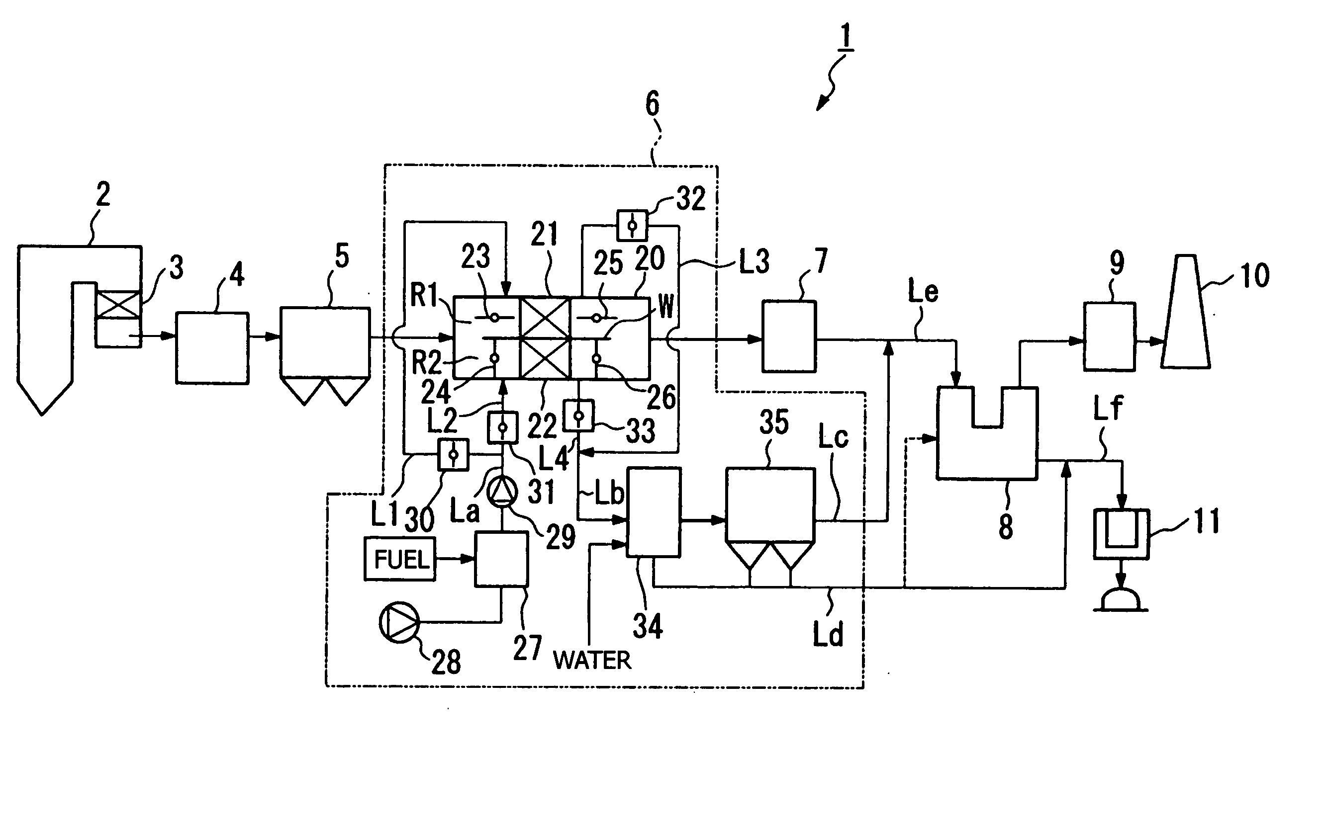
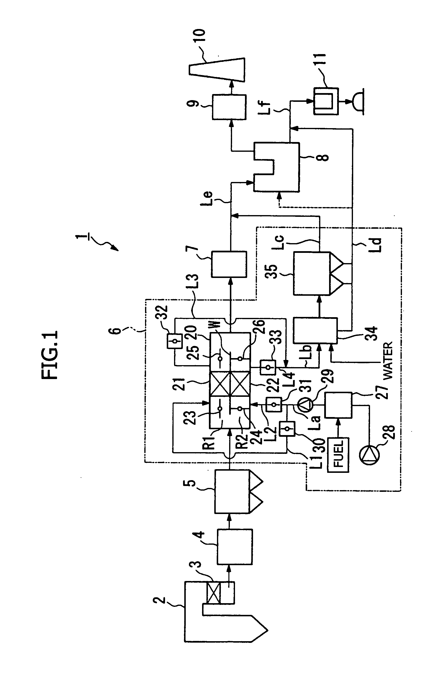
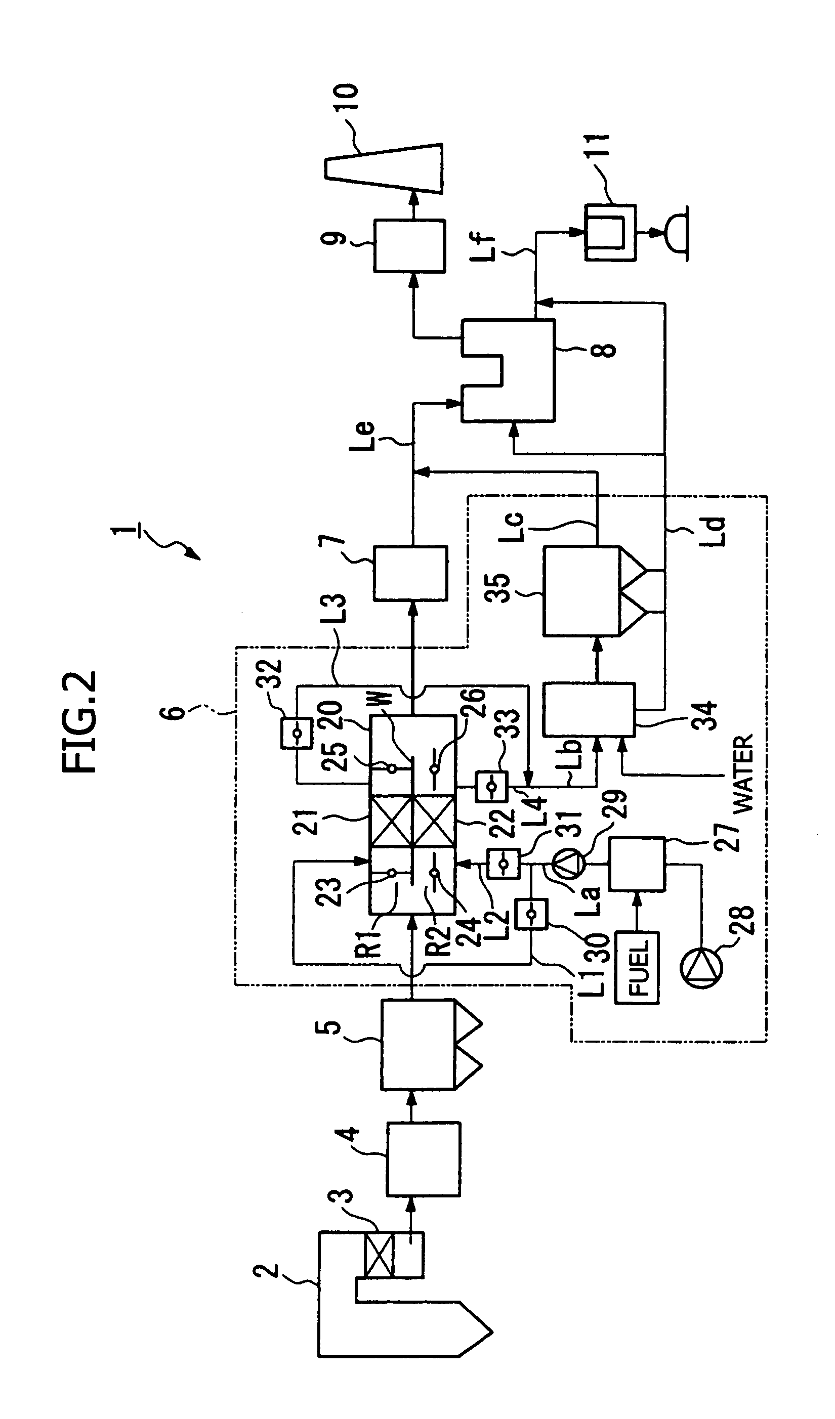
[0045]FIGS. 1 and 2 are flowcharts showing a configuration of an exhaust gas treatment system 1 in accordance with a first embodiment. The exhaust gas treatment system 1 removes NOx, SOx and also mercury contained in exhaust gas discharged from a boiler 2.

[0046] As shown in FIGS. 1 and 2, the exhaust gas treatment system 1 has a denitrification apparatus 3 attached to the boiler 2. The exhaust gas discharged from the boiler 2 is denitrified by the denitrification apparatus 3, and is introduced into a dust collector 5 after passing through an air heater 4. The exhaust gas having passed through the dust collector 5 is introduced into a desulfurization absorption tower 8 after passing through a catalytic oxidation apparatus 6 and a heat exchanger 7. The exhaust gas having passed through the desulfurization absorption tower 8 is discharged into the atmosphere from a stack 10 after passing through a reheater 9.

[0047] In the denitrification apparatus 3, NOx contained i...

second embodiment

[Second Embodiment]

[0077] An exhaust gas treatment system in accordance with a second embodiment will be described with reference to FIGS. 5 to 7.

[0078] The exhaust gas treatment system in accordance with the second embodiment has the same basic configuration as that of the exhaust gas treatment system 1 in accordance with the first embodiment, and only the catalytic oxidation apparatus is different. Therefore, in the description below, this different point is mainly explained. Hereunder, the same reference numerals are applied to the same elements as those in the first embodiment.

[0079] The exhaust gas treatment system in accordance with the second embodiment is provided with four oxidation catalysts capable of performing oxidation treatment independently. FIG. 5 is a transparent perspective view of a catalytic oxidation apparatus body 40, which is an essential portion of the catalytic oxidation apparatus.

[0080] Into the catalytic oxidation apparatus body 40, the exhaust gas hav...

example

[0092] Finally, an experiment in which a fact that the performance of oxidation catalyst can be restored in a period of time of about one-third the time taken for performance deterioration was verified is explained.

[0093]FIG. 9 shows an experimental arrangement. The experimental arrangement has a combustion furnace 70 for burning heavy oil. Exhaust gas generated in the combustion furnace 70 is introduced into an oxidation treatment chamber 76 in which four oxidation catalysts 77 to 80 are disposed at predetermined intervals. To the exhaust gas introduced into the oxidation treatment chamber 76, SO2, HCl and NH3 are added. The experimental arrangement also has a mercury vapor generator 72, and mercury vapor generated in this mercury vapor generator 72 is added to the exhaust gas introduced into the oxidation treatment chamber 76. The mercury vapor generator 72 has a construction in which a vessel 73 which stores mercury is held in a thermostatic chamber 74, and N2 is blown into the ...


PUM

PropertyMeasurementUnit
temperatureaaaaaaaaaa

Abstract

The present invention provides an exhaust gas treatment method including oxidation treatment for converting metallic mercury contained in combustion exhaust gas into mercury chloride; and mercury removal treatment for removing mercury from the combustion exhaust gas by dissolving the mercury chloride in water, wherein a plurality of oxidation catalysts for performing the oxidation treatment are provided, and during the time when the oxidation treatment is performed, at least one of the oxidation catalysts performs catalyst performance restoration treatment without performing oxidation treatment. According to the present invention, the deterioration in mercury removal performance can be restrained even in continuous operation on condition that mercury is oxidized in a low temperature region not higher than 300° C.

Description

FIELD OF THE INVENTION [0001] The present invention relates to an exhaust gas treatment method and an exhaust gas treatment system, which can remove mercury contained in exhaust gas, especially exhaust gas generated by burning coal or heavy oil as a fuel. BACKGROUND OF THE INVENTION [0002] A conventional exhaust gas treatment system will be described with reference to FIG. 12. [0003] Combustion exhaust gas sent from a boiler 111 is introduced into a denitrification apparatus 114. In a flow path to the denitrification apparatus 114, an ammonia injection apparatus 112 is provided to inject NH3, which is supplied from an ammonia tank 113, into the exhaust gas. For the exhaust gas into which NH3 is injected, NOx is converted into nitrogen in the denitrification apparatus 114 by selective reduction reactions expressed in Equations (1) and (2), by which denitrification is accomplished.4NO+4NH3+O2→4N2+6H2O  (1)NO+NO2+2NH3→2N2+3H2O  (2)[0004] The desulfurized exhaust gas passes through an a...

Claims


Application Information

Patent Timeline
Patent Type & Authority Applications(United States)
IPC IPC(8): B01D53/34B01D53/56B01D53/50B01D53/64B01D53/86B01D53/94B01J8/00C10J3/48C10J3/82
CPCB01D53/8665B01D2257/602C10J3/485C10J3/82C10K1/007C10K1/02C10K3/02C10J2300/1884C10K1/004
Inventor HONJO, SHINTAROIIDA, KOZOOKADA, KENICHITAKEUCHI, YASUHIROTABATA, MASANORI
Owner MITSUBISHI HEAVY IND LTD
Why Eureka
Try Eureka