Transmission

Active Publication Date: 2014-03-20
SUBARU CORP
View PDF5 Cites 1 Cited by
  • Summary
  • Abstract
  • Description
  • Claims
  • Application Information

AI Technical Summary

Benefits of technology

[0011]The present invention has been designed in consideration of the circumstances described above, and an object thereof is to provide a transmission that achieves

Problems solved by technology

When spike torque is generated during a gear shift in this manner, an impact sound is generated by the engagement between the key and the dog, noise is generated when an outer race of a bearing that supports the shaft impinges on a transmission case, and so on.
Moreover, the spike torque may generate torsion in the shaft, which causes vibration in a drive wheel and the transmission case.
In the transmission disclosed in JP-T No. 2010-510464, however, noise and vibration are not suppressed efficiently, and there

Method used


Image

  • Transmission
  • Transmission
  • Transmission

Examples


Example

First Example

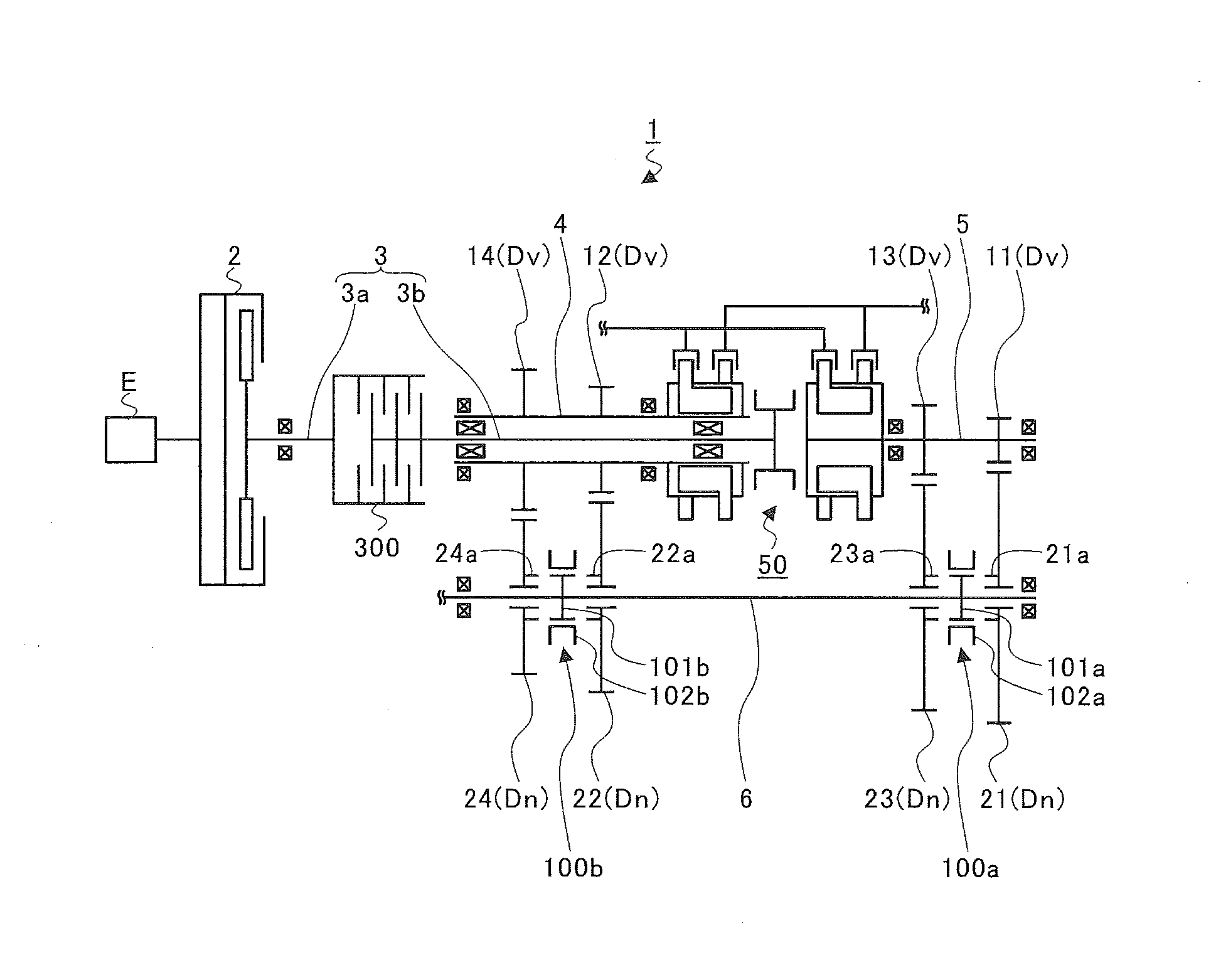
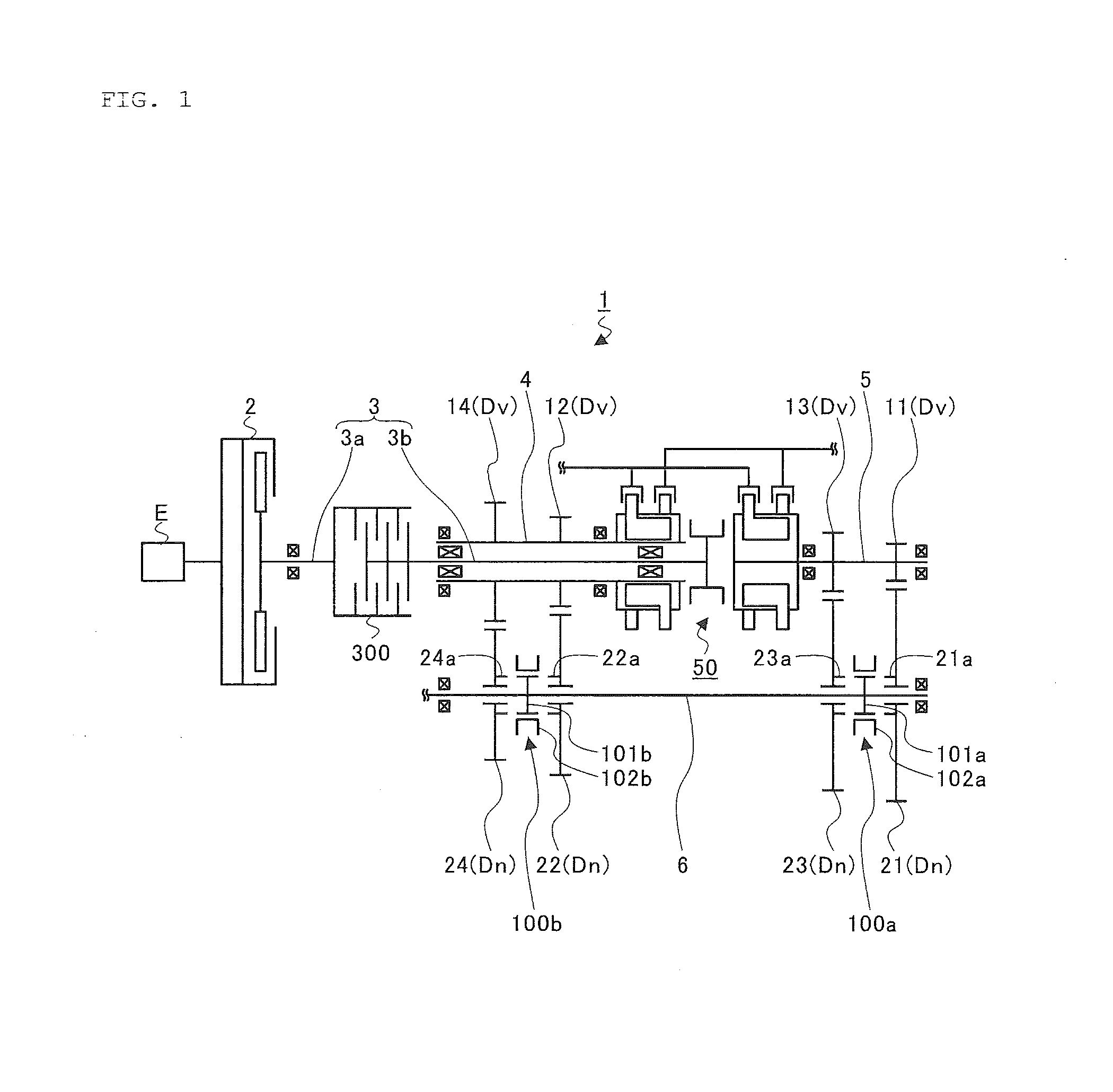
[0033]FIG. 1 is a schematic view showing a transmission 1 for a vehicle according to a first Example. The transmission 1 according to this example transmits a driving force of an engine E to a drive wheel, and includes an input shaft 3 that is supported to be free to rotate by a bearing held on a transmission case, and connected to a crankshaft of the engine E via a startup clutch 2. The input shaft 3 is rotated by the driving force of the engine E, and is constituted by a first input shaft 3a and a second input shaft 3b disposed respectively on an upstream and a downstream of a transmission path for transmitting power from the engine E. A damping mechanism 300 is provided between the first input shaft 3a and the second input shaft 3b. As will be described in more detail below, when spike torque that generates torque variation at or beyond a set torque occurs in the input shaft 3, the damping mechanism 300 generates a sliding motion to cause the first input shaft 3a and...

Example

Second Example

[0094]FIG. 11 is a schematic view showing a transmission 1B for a vehicle according to a second example, and FIG. 12 is a schematic sectional view illustrating a shaft switching mechanism 60 according to the second example. In the second example shown in FIGS. 11 and 12, a configuration of the shaft switching mechanism 60 differs from that of the shaft switching mechanism 50 according to the first example, but all other configurations are identical to the first example. Hence, identical reference symbols have been allocated to the configurations that are identical to the first example, and description thereof has been omitted. The configuration of the shaft switching mechanism 60 will be described below.

[0095]The transmission 1B includes the shaft switching mechanism 60 for selectively switching the transmission path of the rotary power of the input shaft 3 between the first main shaft 4 and the second main shaft 5. Similarly to the shaft switching mechanism 50, the sh...


PUM


Abstract

In a transmission, an input shaft connected to a startup clutch includes a first input shaft and a second input shaft. Drive gears are fixed to a first main shaft and a second main shaft, and driven gears are provided on an output shaft to be free to rotate relative thereto. The driven gears are connected to and disconnected from the output shaft by a gear switching mechanism. A shaft switching mechanism that switches a power transmission path between the first main shaft and the second main shaft is provided on the first main shaft, the second main shaft, and the second input shaft. A damping mechanism is provided between the first input shaft and the second input shaft in order to cut spike torque generated when the power transmission path is switched, to a set torque.

Description

CROSS-REFERENCE TO RELATED APPLICATIONS[0001]The present application claims priority from Japanese Patent Application No. 2012-202463, filed on Sep. 14, 2012, the entire contents of which are hereby incorporated by reference.BACKGROUND[0002]1. Technical Field[0003]The present invention relates mainly to transmissions for vehicles.[0004]2. Related Art[0005]Conventional transmissions include a transmission disclosed in Japanese Unexamined Patent Application Publication (Translation of PCT Application) (JP-T) No. 2009-536713. This transmission includes a low gear and a high gear that are attached to an output shaft so as to freely rotate, a hub fixed to the shaft between the low gear and the high gear, and a first key and a second key that are attached to the hub so as to move freely in an axial direction and rotate integrally therewith in a circumferential direction.[0006]According to this transmission, when the first key and the second key are moved to the low gear by an actuator dur...

Claims


Application Information

Patent Timeline
IPC IPC(8): F16H3/083
CPCF16H3/083F16D7/027F16D11/10F16D21/04F16D47/02F16H63/30F16H3/0915F16H57/0006F16H2200/2094F16H2063/3093Y10T74/19479
Inventor UKON, YASUYUKI
Owner SUBARU CORP
Why Eureka
Try Eureka