Folding solar canopy assembly

a solar panel and assembly technology, applied in the direction of heat collector mounting/support, pv power plants, light and heating equipment, etc., can solve the problems of inefficient and overly expensive prior known systems for elevating structures for supporting solar collector panels, and known systems take an excessive amount of time to install, etc., to achieve simple unfolding and simple

Active Publication Date: 2014-03-20
ENGIE SERVICES U S INC
View PDF9 Cites 35 Cited by
  • Summary
  • Abstract
  • Description
  • Claims
  • Application Information

AI Technical Summary

Benefits of technology

[0007]The invention includes a solar canopy a structure capable of folding into a compact form for transporting, and for simple unfolding for attachment to a base. The structure comprises a plurality of hingably interconnected solar panel arrays each having a plurality of solar panels, a solar panel support channel, and a support beam; wherein the plurality of solar panels is attached to top portions of the solar panel support channel, and a bottom portion of the solar panel support channel is attached to a top portion of the support beam, the support beam having a hinged joint for cooperating in folding into mutual, near coplanar juxtaposition; and whereby the structure, when unfolded comprises a solar canopy and is L-shaped viewed on end.
[0008]In another embodiment, the invention includes a solar canopy a solar canopy structure capable of folding into a compact form for transporting, and for simple unfolding for attachment to a foundation, the structure comprising one or more support beams for supporting a plurality of solar panel support channels and a plurality of solar panels, the support beams having an integral hinge for cooperating in folding into a compact form for transporting; and whereby the structure, when unfolded comprises a solar canopy and is L-shaped viewed on end.
[0009]These and other features and advantages of the present invention will be made more apparent through a consideration of the following detailed description of a preferred embodiment of the invention. In the course of this description, frequent reference will be made to the attached drawings.

Problems solved by technology

Beyond the photo-electro voltaic cell technology itself are the problems of placement and support of the solar collector panels.
Prior known systems for elevated structures for supporting the solar collector panels are inefficient and overly expensive since they require excessive amounts of materials, particularly steel support elements, and on-site construction.
Also, known systems take an excessive amount of time to install.

Method used


Image

  • Folding solar canopy assembly
  • Folding solar canopy assembly
  • Folding solar canopy assembly

Examples


Embodiment Construction

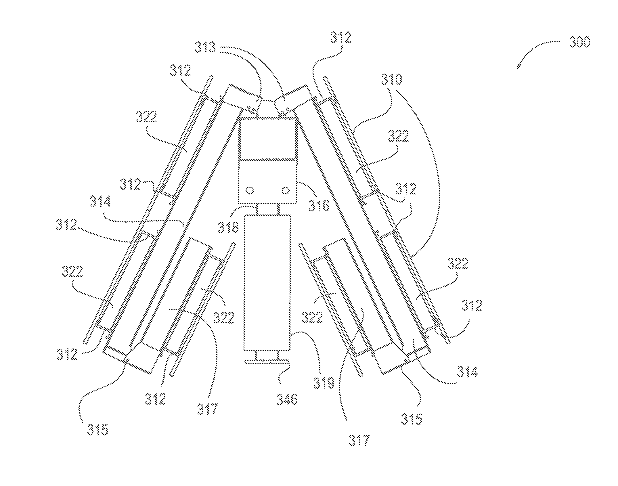
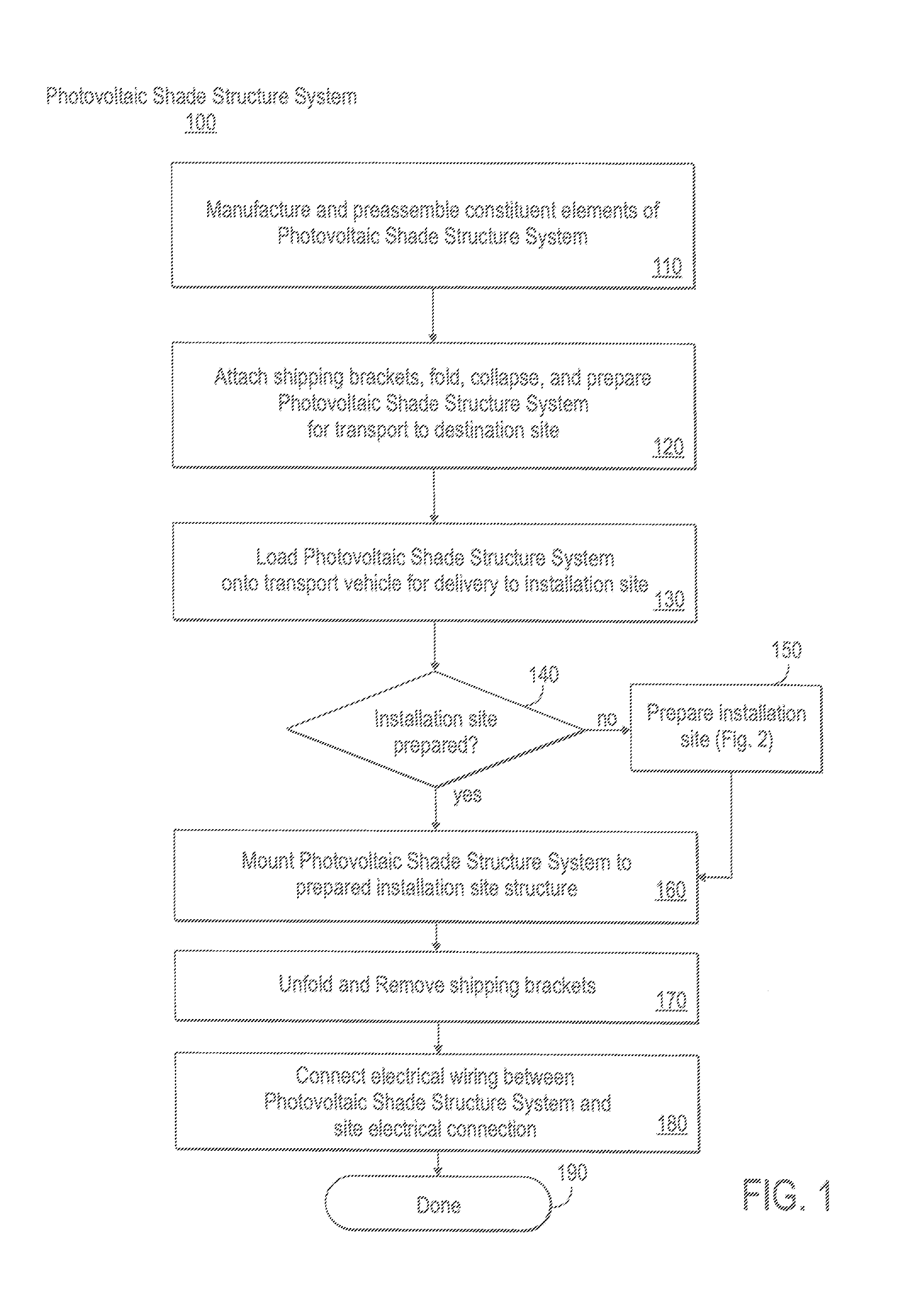
[0031]Field labor prices are expensive. By designing a folding structure so it can be shipped, a majority of the field labor is moved into the factory. This allows for lower labor costs going into the installation of Photovoltaic Solar Shade Structures. A known method of partially addressing this problem is by manufacturing portions of the structures in the factory, then shipping those portions out in parts, and assembling them in the field. The Manufactured Folding Photovoltaic Shade Structure of the invention allows for more components to be connected, wired, tested and even commissioned in the factory before being sent to the site for installation.

[0032]The invention includes a one or two or multiple column photovoltaic shade structure which is fully assembled in a factory. This assembly in some embodiments includes electrical panels, inverters, combiner boxes, lights, conduit, AC panel board or DC combiner, pull boxes, wire management components, strut, conduit, monitoring equip...


PUM


Abstract

A structure capable of folding into a compact form for transporting, and for simple unfolding for attachment to a base, the structure including: two or more hingably interconnected solar panel arrays each having a two or more of solar panels, a solar panel support channel, and a support beam; wherein the two or more solar panels are attached to top portions of the solar panel support channel, and a bottom portion of the solar panel support channel is attached to a top portion of the support beam, the support beam having a hinged joint for cooperating in folding into mutual, near coplanar juxtaposition; and where the structure, when unfolded includes a solar canopy and is L-shaped viewed on end.

Description

COPYRIGHT NOTICE AND AUTHORIZATION[0001]This patent document contains material which is subject to copyright protection.[0002]©Copyright 2012. Chevron Energy Solutions Company, a division of Chevron U.S.A. Inc. All rights reserved.[0003]With respect to this material which is subject to copyright protection. The owner, Chevron Energy Solutions has no objection to the facsimile reproduction by any one of the patent disclosure, as it appears in the Patent and Trademark Office patent files or records of any country, but otherwise reserves all rights whatsoever.FIELD OF THE INVENTION[0004]This invention relates to system and method for a foldable solar canopy.BACKGROUND OF THE INVENTION[0005]Solar energy is a clean, renewal energy source. Photo-electro voltaic cell technology is increasing rapidly and makes installation of solar collector panels housing the photo-electro voltaic cells more and more economically feasible. Beyond the photo-electro voltaic cell technology itself are the pro...

Claims


Application Information

Patent Timeline
Patent Type & Authority Applications(United States)
IPC IPC(8): H01L31/042H01L31/045
CPCH01L31/045H01L31/0422H02S30/20H02S20/10Y02E10/47F24S2025/012F24S25/33F24S2030/115F24S25/12F24S25/70Y02E10/50H01L31/042
Inventor HAMILTON, COLLIN
Owner ENGIE SERVICES U S INC
Why Eureka
Try Eureka