Vibrating actuator
a technology of actuators and actuators, applied in the direction of mechanical vibration separation, generators/motors, instruments, etc., can solve the problems of shortening the life of motors, consuming a lot of time to reach a target amount of vibration, and difficult to implement an appropriate amount of vibration in the touchscreen, so as to increase the quantity of vibrations and reduce power consumption.
- Summary
- Abstract
- Description
- Claims
- Application Information
AI Technical Summary
Benefits of technology
Problems solved by technology
Method used
Image

Examples
first embodiment
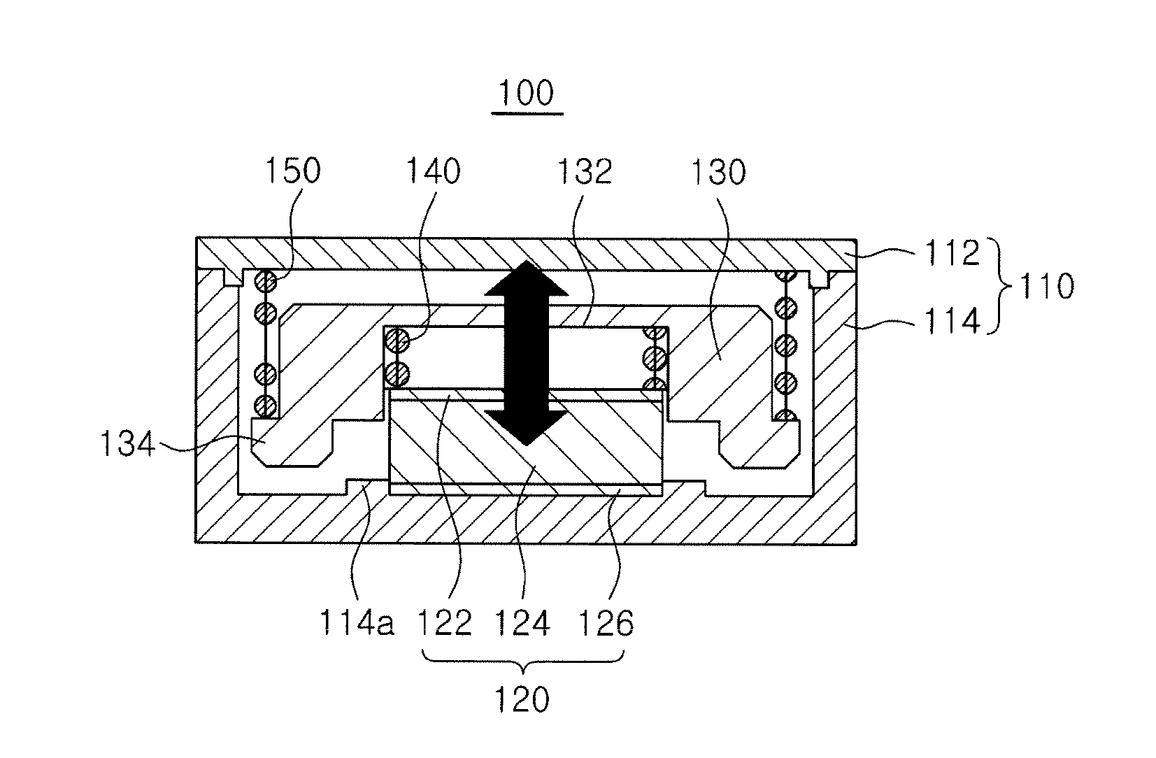
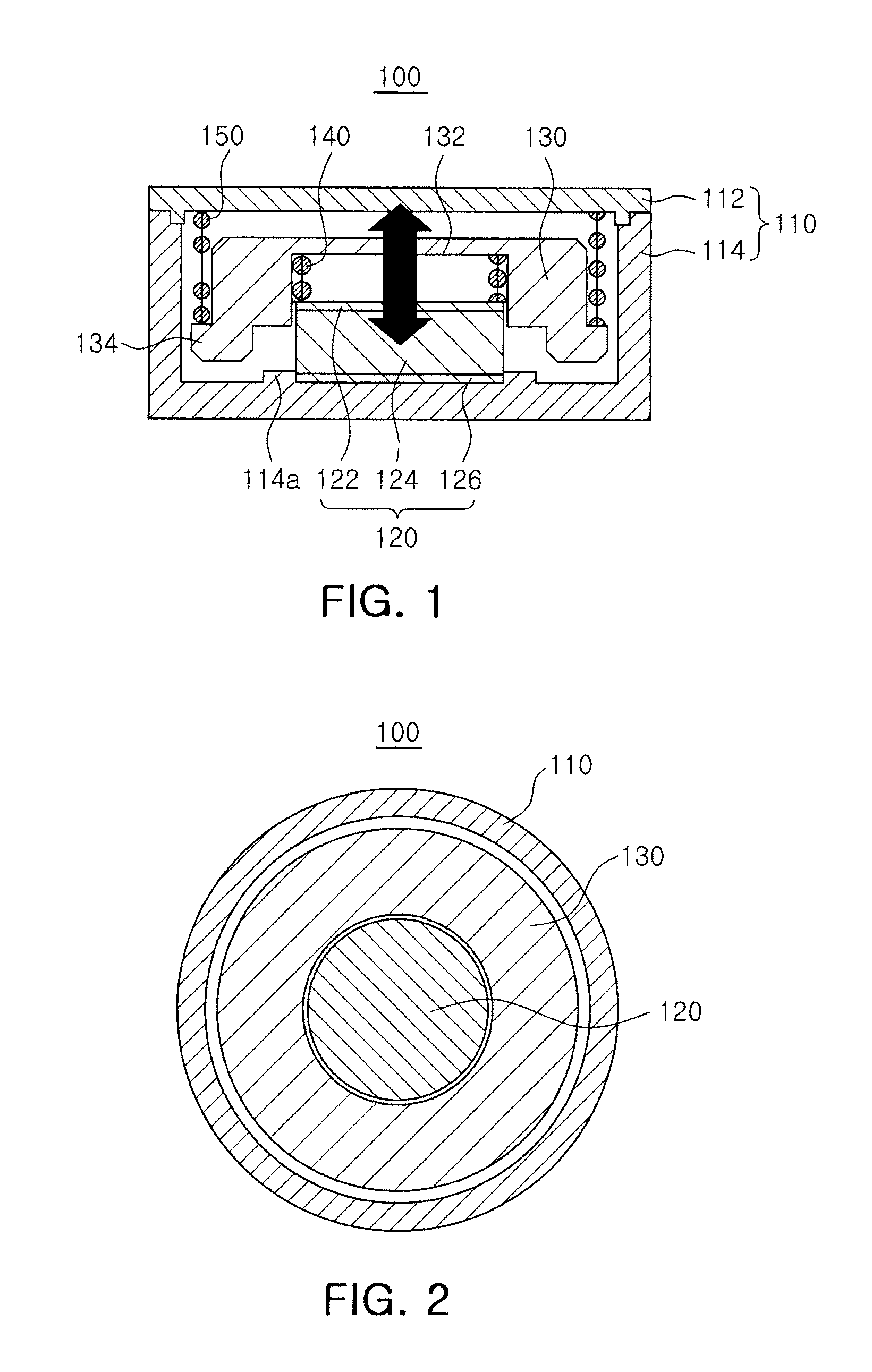
[0052]Referring to FIGS. 1 through 3, a vibrating actuator 100 according to the present invention may include the housing 110 forming an outer casing of the vibrating actuator 100, a mass body 130, a first elastic member 140, a second elastic member 150, and a piezoelectric element 120.
[0053]The housing 110 may include a lower housing 114 of which one portion is opened and providing a predetermined inner space and an upper housing 112 joined to the opened portion of the lower housing 114.
[0054]The inner space may accommodate the mass body 130, the first elastic member 140, the second elastic member 150, the piezoelectric element 120, and the like, and the housing 110 may also integrally be formed.
[0055]A portion of the inner surface of the housing 110 may be provided with an outer wall 114a protruded to correspond to an outer diameter of the piezoelectric element 120 to be described below and an inner surface of the outer wall 114a may have the piezoelectric element 120 inserted the...
second embodiment
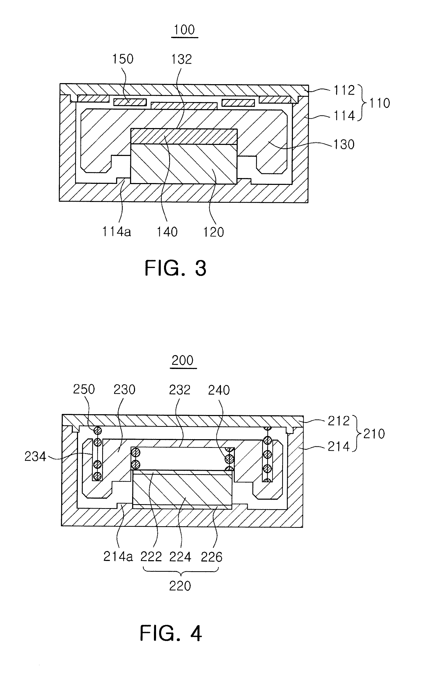
[0087]FIG. 4 is a schematic cross-sectional view illustrating a vibrating actuator according to the present invention.
[0088]Referring to FIG. 4, a vibrating actuator 200 according to a second embodiment of the present invention is the same as the vibrating actuator 100 according to the first embodiment except for a mass body 230 and a second elastic member 250 and therefore, the description other than the mass body 230 and the second elastic member 250 will be omitted.
[0089]A shape of a radial cross section of the mass body 230 may be variously formed to have a circular, a rectangular, a regular square, a ring shape, and the like, according to the shape of the housing 110 and the internal components.
[0090]Further, in order to prevent a piezoelectric element 220 mounted on a portion of an inner surface of the housing 210 from coming into contact with the mass body 230 during the vibration process, a contact preventing portion 232 in which at least a portion of the bottom surface of t...
third embodiment
[0094]FIG. 5 is a schematic cross-sectional view illustrating a vibrating actuator according to the present invention.
[0095]Referring to FIG. 5, a vibrating actuator 300 according to a third embodiment of the present invention is the same as the vibrating actuator 100 according to the first embodiment except for a mass body 330, a first elastic member 340 and a second elastic member 350, and therefore, the description other than the mass body 330, the first elastic member 340, and the second elastic member 350 will be omitted.
[0096]The mass body 330 may include a horizontal portion 332 and an extension 334 extending downwardly from an outside of the horizontal portion 332.
[0097]An inner diameter of the extension 334 may be larger than an outer diameter of the piezoelectric element 320 and as a result, the piezoelectric element 320 may be prevented from coming into contact with the extension 334 during the vibration process.
[0098]Further, the mass body 330 may be provided with a prot...
PUM
 Abstract
Description
Claims
Application Information
 - R&D
- Intellectual Property
- Life Sciences
- Materials
- Tech Scout
- Unparalleled Data Quality
- Higher Quality Content
- 60% Fewer Hallucinations
Browse by: Latest US Patents, China's latest patents, Technical Efficacy Thesaurus, Application Domain, Technology Topic, Popular Technical Reports.
© 2025 PatSnap. All rights reserved.Legal|Privacy policy|Modern Slavery Act Transparency Statement|Sitemap|About US| Contact US: help@patsnap.com