Display device and light adjusting method thereof

a technology of a display device and a light adjusting method, which is applied in the direction of instruments, computing, electric digital data processing, etc., can solve the problems of affecting user's viewing quality, extra circuitry structure may reduce the opening ratio of pixels, and may contain characteristics that are not compatible with the same factory, so as to reduce or avoid the occurrence of mura effect and improve the viewing quality of users.

Active Publication Date: 2014-03-20
INNOLUX CORP
View PDF6 Cites 22 Cited by
  • Summary
  • Abstract
  • Description
  • Claims
  • Application Information

AI Technical Summary

Benefits of technology

[0013]To sum up, an exemplary embodiment of the present disclosure provides a display device and the light adjusting method thereof which can adjust the offset voltage outputted to the driver transistor according to the brightness of the display to have the driver transistor adjusting the threshold voltage thereof based on the offset voltage. Accordingly, the driving current outputted by the driver transistor can be configured to adjust the brightness of the light emitting diode. The display device may thus reduce or avoid the occurrence of mura effect thereby improve the viewing quality of the user.

Problems solved by technology

However, different semiconductors manufactured by same factory may contain discrepancies in the characteristics (e.g., the threshold voltage) thereof.
In view of displayed image, the discrepancies in the driving current may cause mura in brightness of the image thereby affecting user's viewing quality.
However, it is known that extra circuitry structure may reduce the opening ratio of pixels.

Method used


Image

  • Display device and light adjusting method thereof
  • Display device and light adjusting method thereof
  • Display device and light adjusting method thereof

Examples


Embodiment Construction

[0024]Reference will now be made in detail to the exemplary embodiments of the present disclosure, examples of which are illustrated in the accompanying drawings. Wherever possible, the same reference numbers are used in the drawings and the description to refer to the same or like parts.

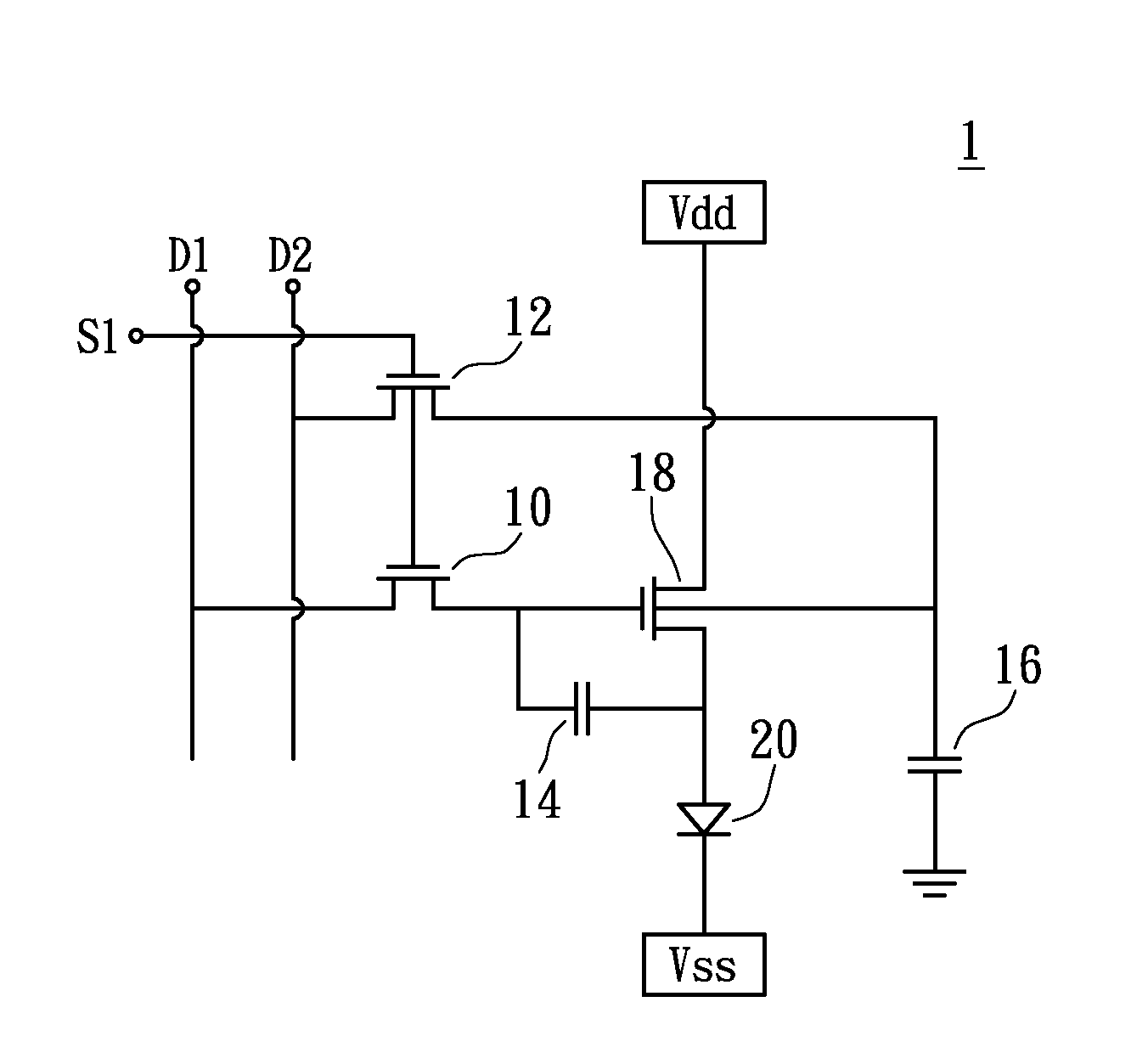
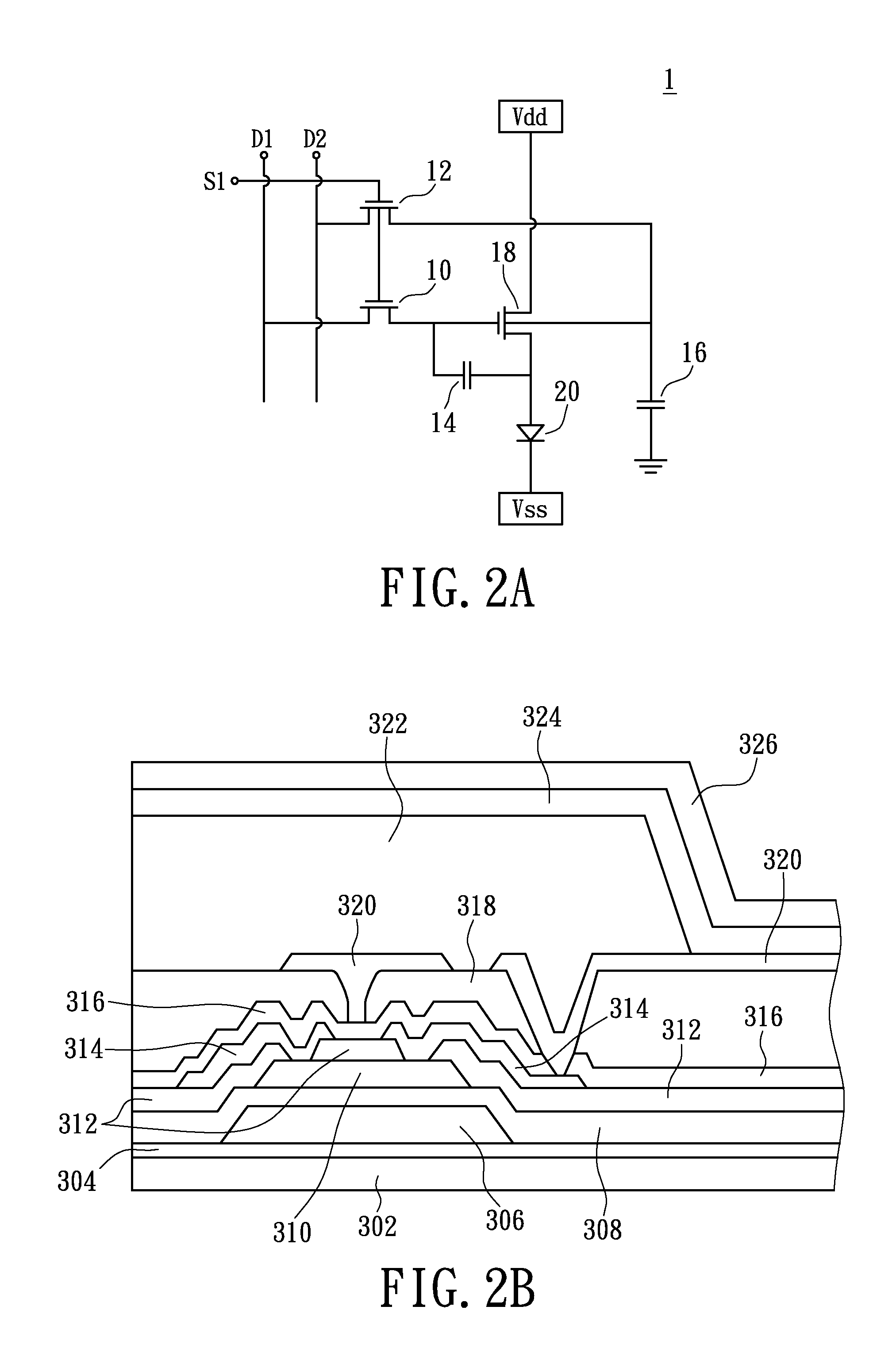
[0025]Please refer to FIG. 2A and FIG. 2B at same time. FIG. 2A shows a partial schematic diagram illustrating a display device provided in accordance to a first exemplary embodiment of the present disclosure. FIG. 2B shows a cross sectional diagram illustrating the display device provided in accordance to the first exemplary embodiment of the present disclosure. The display device 1 has a plurality of pixels, and at least one of the pixels has a light emitting diode 20 and a driving module (including components 10, 12, 14, 16, and 18) for driving the light emitting diode 20. Specifically, the first switch circuit 10 is coupled to a gray scale data line D1, a first capacitor 14, and a driver transis...


PUM


Abstract

The present disclosure provides a display device including a light emitting diode and a driving module. The driving module drives the light emitting diode. The driving module includes a first switch circuit, a second switch circuit, and a driver transistor. The first switch circuit selectively writes a gray scale voltage in a first capacitor. The second switch circuit selectively writes an offset voltage in a second capacitor. The driver transistor is coupled to the light emitting diode, the first capacitor, and the second capacitor. The driver transistor adjusts a driving current being outputted to the light emitting diode according to the gray scale voltage and the offset voltage. The gray scale voltage adjusts the voltage difference between the gate and the source of the driver transistor, while the offset voltage adjusts a threshold voltage of the driver transistor.

Description

BACKGROUND[0001]1. Technical Field[0002]The present disclosure relates to a display device and a light adjusting method thereof, in particular, to a display device and a light adjusting method thereof for adjusting the threshold voltage of the driver transistor.[0003]2. Description of Related Art[0004]Display device for displaying images has been widely used in manufacturing and daily life along with widespread of the multimedia apparatus such as computer, cell phone and television. In a typical Organic Light Emitting Diode (OLED) display device, multiple transistors are utilized to control and drive light emitting diode to have each associated light emitting diode generating proper brightness.[0005]For instance, FIG. 1 shows a schematic diagram illustrating a conventional OLED display device. As shown in FIG. 1, the display device 9 has a switching transistor 90, a capacitor 92, a driver transistor 94, and a light emitting diode 96. The switching transistor 90 being controlled by a...

Claims


Application Information

Patent Timeline
Patent Type & Authority Applications(United States)
IPC IPC(8): G09G5/10G09G3/32
CPCG09G3/3291G09G5/10G09G3/3233G09G2300/0819G09G2300/0852G09G2320/0295G09G2320/043G09G2360/147G09G2320/0233G09G2320/0626G09G3/3283G09G3/32
Inventor YANG, CHENG-CHUNGCHEN, LIANG-LUCHEN, CHUN YUGUO, HONG-RU
Owner INNOLUX CORP
Why Eureka
Try Eureka