Power Conversion Apparatus and Control Method Thereof

a technology of power conversion apparatus and control method, which is applied in the direction of power conversion system, ac-ac conversion, electrical apparatus, etc., can solve problems such as interfering with the other control

Inactive Publication Date: 2014-03-20
HITACHI LTD
View PDF4 Cites 30 Cited by
  • Summary
  • Abstract
  • Description
  • Claims
  • Application Information

AI Technical Summary

Benefits of technology

[0011]It is an object of the present invention to provide a power conversion apparatus which can withstand unevenness of capacitor voltages while preventing a superimposed voltage from appearing on a DC side terminal, and a control method thereof.
[0016]According to the present invention, the power conversion apparatus can bring a balance against unevenness of a capacitor voltage while preventing a superimposed voltage for a balance from appearing on a DC terminal. More specifically, an effect that energy or a voltage of the energy storage device can be balanced or an arbitrary imbalance can be generated without causing one power conversion apparatus to interfere with control of another power conversion apparatus is obtained in an FC, an HVDC system, or a BTB system.

Problems solved by technology

However, there is a problem that when a zero-phase sequence voltage is superimposed on an output voltage command value of each arm against unevenness of capacitor voltages in each unit converter, the superimposed zero-phase sequence voltage appears on a DC side terminal.
In this case, one zero-phase sequence voltage through arm balance control of a ZC-MMC appears on a common DC terminal and interferes with the other control.

Method used


Image

  • Power Conversion Apparatus and Control Method Thereof
  • Power Conversion Apparatus and Control Method Thereof
  • Power Conversion Apparatus and Control Method Thereof

Examples


first embodiment

[0028]A first embodiment of the present invention will be described below with reference to the accompanying drawings of the embodiment.

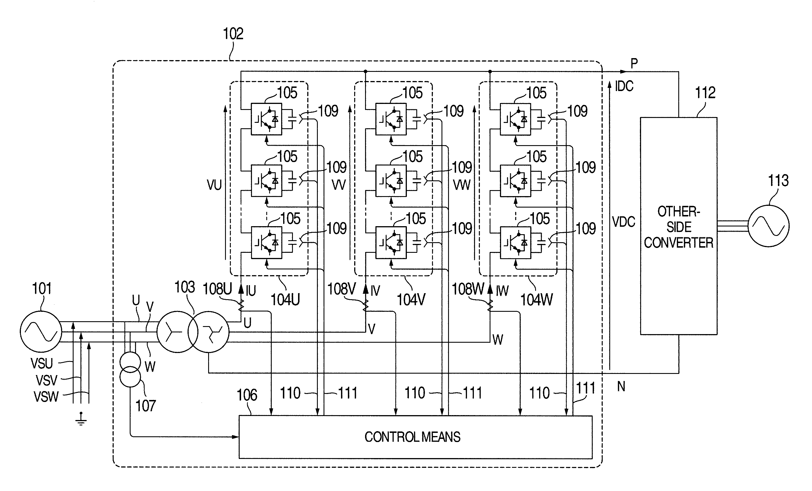
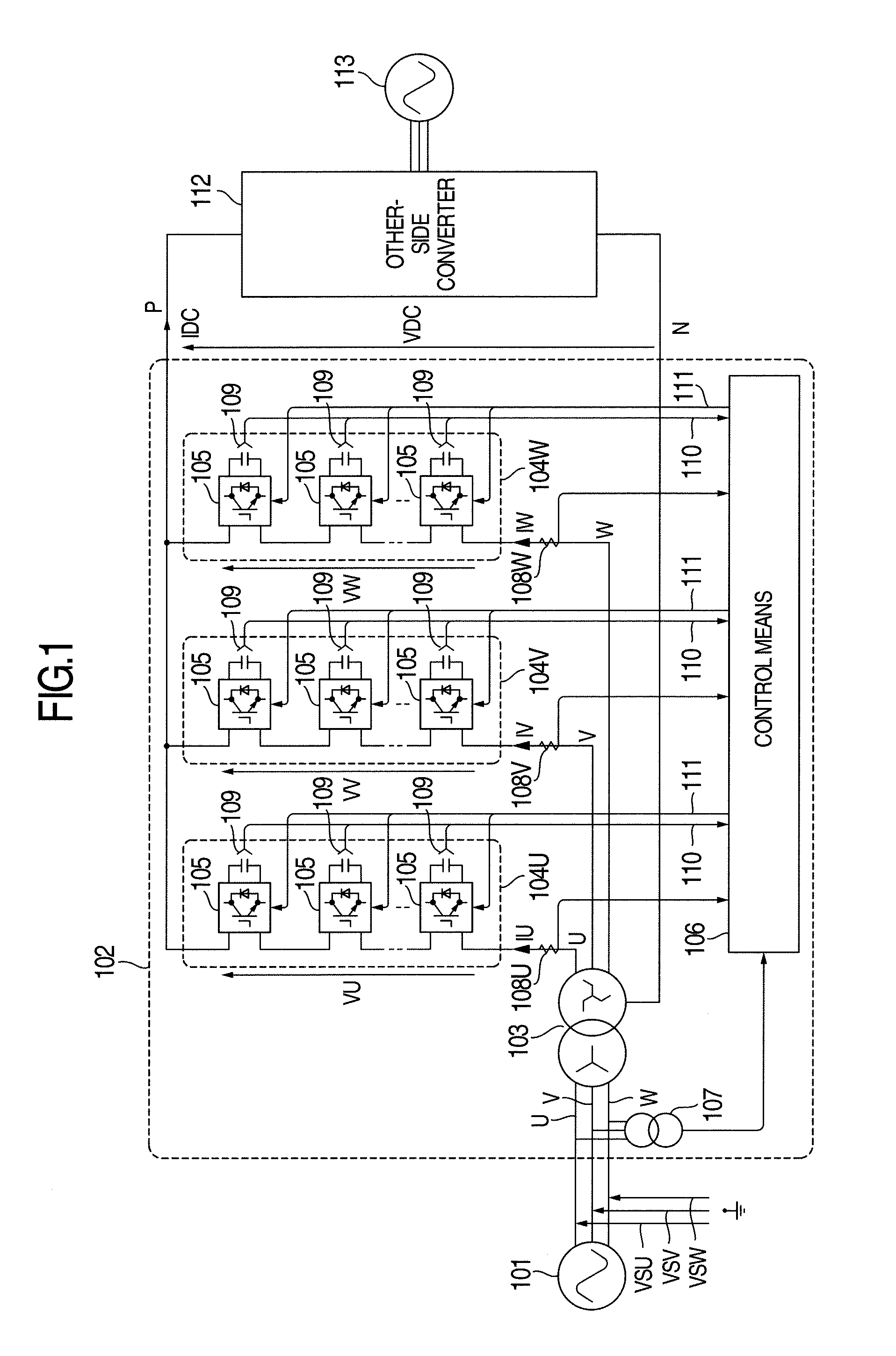
[0029]The present invention has a configuration in which in a power conversion apparatus in which a bidirectional chopper circuit is used as a unit converter, three circuits in which three arms in which a plurality of the bidirectional chopper circuits are connected in series and three secondary windings of a transformer are connected in series, respectively, are connected in parallel, one terminal of the parallel connection point is set as a DC positive side terminal, the other terminal thereof is set as a DC negative side terminal, and a primary winding of the transformer is connected to a three-phase power system, when a negative-phase-sequence current flows through the arm according to a difference of an average value for each arm of a voltage in the capacitor, a control means for having a function of balancing an average value for each arm of a...

second embodiment

[0124]A second embodiment of the present invention will be described.

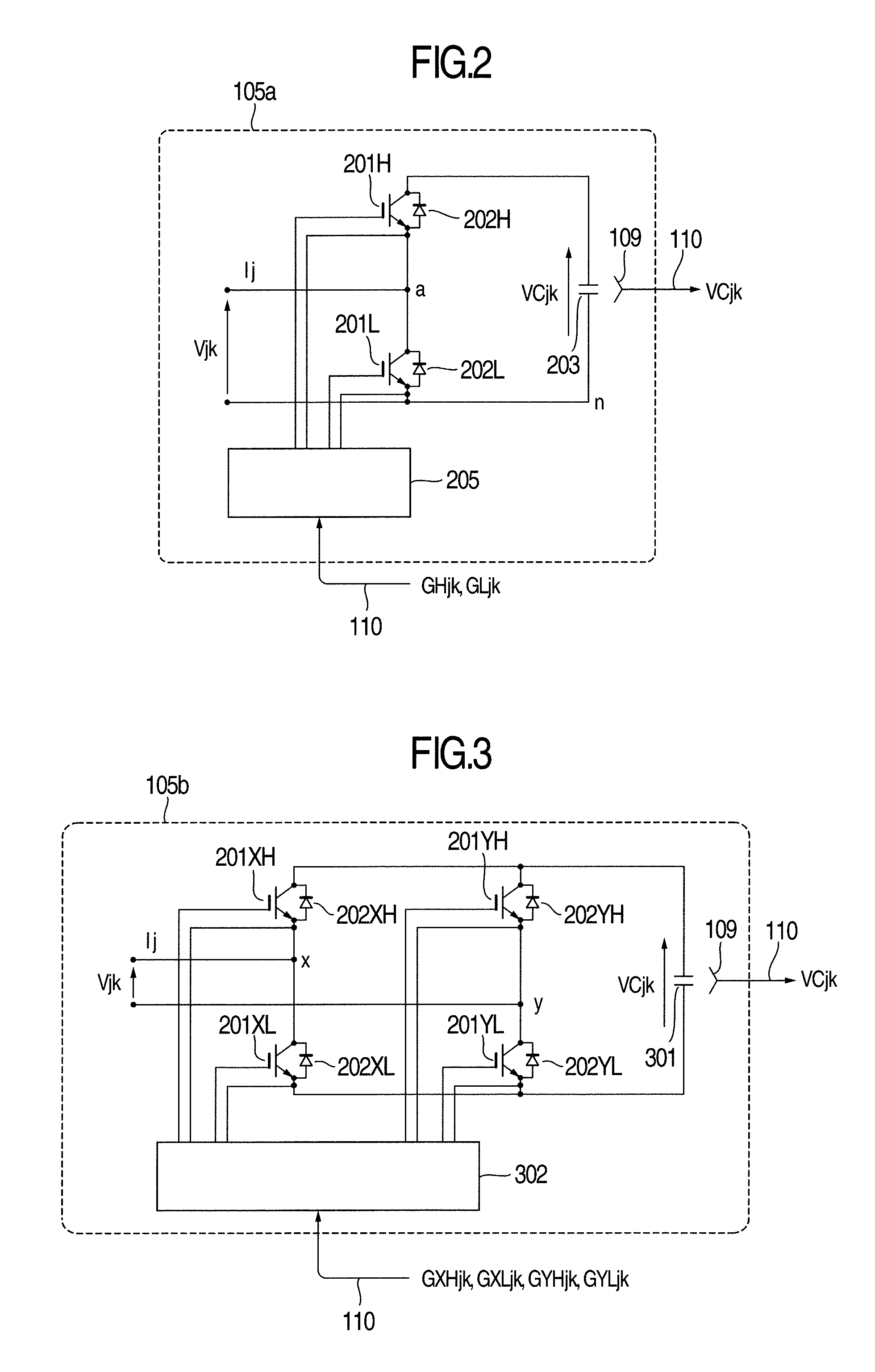
[0125]In the first embodiment, the unit converter 105a (FIG. 2) in the bidirectional chopper circuit system is used in each of the arms 104U, 104V, and 104W. The present embodiment has a configuration in which a part or all of unit converters 105 are replaced by the unit converters 105b (FIG. 3) in the full-bridge circuit system illustrated in FIG. 3.

[0126]According to the present embodiment, in addition to the effects to be obtained in the first embodiment, an effect in which a voltage VDC between a DC positive side terminal (point P) and a DC negative side terminal (point N) can be controlled so as to be positive, zero, or negative is obtained.

[0127]Only points in which the present embodiment differs from the first embodiment will be described below.

[0128]First, an internal configuration of the unit converter 105b in the full-bridge circuit system will be described with reference to FIG. 3.

[0129]A main circuit of...

third embodiment

[0142]A third embodiment of the present invention will be described with reference to FIG. 9.

[0143]The present embodiment differs from the first and second embodiments in that a transformer 901 in which an open winding is used as the secondary winding is used in place of the transformer 103 and in that the arms 104U, 104V, and 104W are divided so as to be arms 903U, 903V, and 903W.

[0144]In the present embodiment, an effect that a potential of a transformer can be freely changed is obtained in addition to the same effects as those of the first and second embodiments.

[0145]Points in which the present embodiment differs from the first and second embodiments will be described below.

[0146]The secondary winding of a transformer 902 is an open winding, and the transformer 902 includes at least six terminals at points u1, u2, v1, v2, w1, and w2. An internal configuration of the transformer 902 will be described later.

[0147]One part of the U-phase arm 903U is connected to a DC positive side ...


PUM


Abstract

In the present invention, provided is a power conversion apparatus in which at least one energy storage element and at least one switching element are included, a plurality of series circuits of a transformer winding and an arm in which one or a plurality of at least two-terminal unit converters which depend on ON / OFF of the switching element and supply a zero voltage or a voltage depending on a voltage of the energy storage element are connected in series are connected in parallel, and a multi-phase power source or a multi-phase load is connected to another winding of the transformer, and the parallel-connection point is set as a DC terminal, and which includes means for controlling a current flowing through each of the arms to have a phase and amplitude different from each other.

Description

BACKGROUND OF THE INVENTION[0001]The present invention relates to a power conversion apparatus and a control method thereof. More particularly, the present invention relates to a power conversion apparatus which includes an arm configured by connecting one or a plurality of unit converters in series and which is suitable to convert AC power into DC power or antily, and a control method thereof.[0002]In recent years, a number of power conversion apparatus which convert AC into DC or DC into AC are used. A power conversion apparatus which uses unit converters is known as this kind of power conversion apparatus. For example, when a plurality of unit converters are connected in series, a power conversion apparatus which withstands a high voltage is relatively easily obtained. A unit converter has an energy storage element such as a capacitor, and supplies a voltage of the energy storage element to an output terminal by operating a semiconductor switching element.[0003]This kind of power...

Claims


Application Information

Patent Timeline
Patent Type & Authority Applications(United States)
IPC IPC(8): H02M7/217
CPCH02M7/2173H02M5/10H02M5/4585H02M7/483H02M7/5388H02M7/4835
Inventor INOUE, SHIGENORIKATOH, SHUJIBANDO, AKIRAKIYOFUJI, YASUHIROEGUCHI, YOSHIOICHINOSE, MASAYAYAMAMOTO, TAKAYOSHI
Owner HITACHI LTD
Why Eureka
Try Eureka