System and method for discrete gain control in hybrid MIMO RF beamforming for multi layer MIMO base station

a beamformer and hybrid technology, applied in the field of multi-layer mimo base station rf beamformer, can solve the problems of reducing the gain of the beamformer, and affecting the performance of the beamformer

Inactive Publication Date: 2014-03-20
MAGNOLIA BROADLAND INC
View PDF0 Cites 68 Cited by
  • Summary
  • Abstract
  • Description
  • Claims
  • Application Information

AI Technical Summary

Benefits of technology

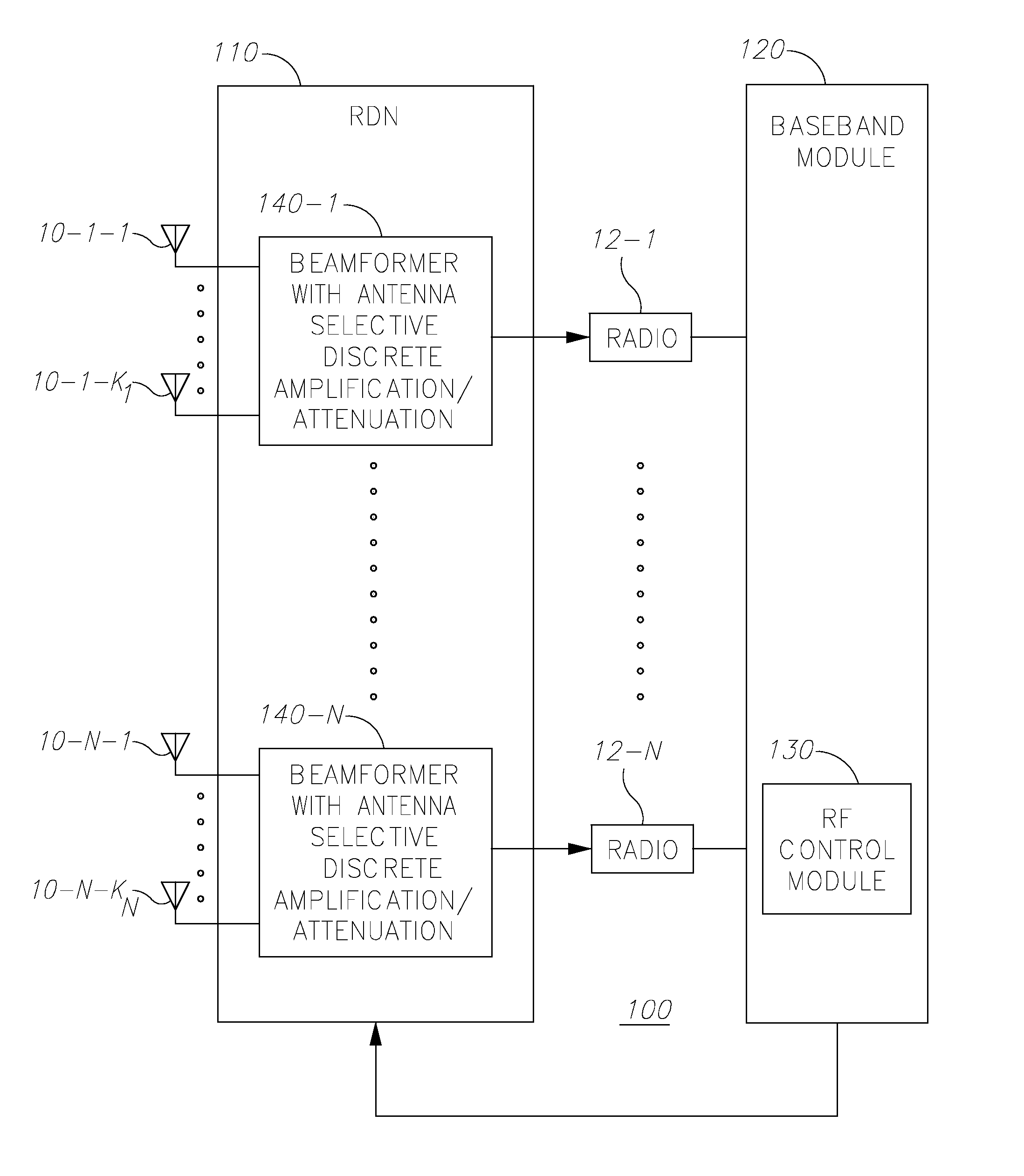
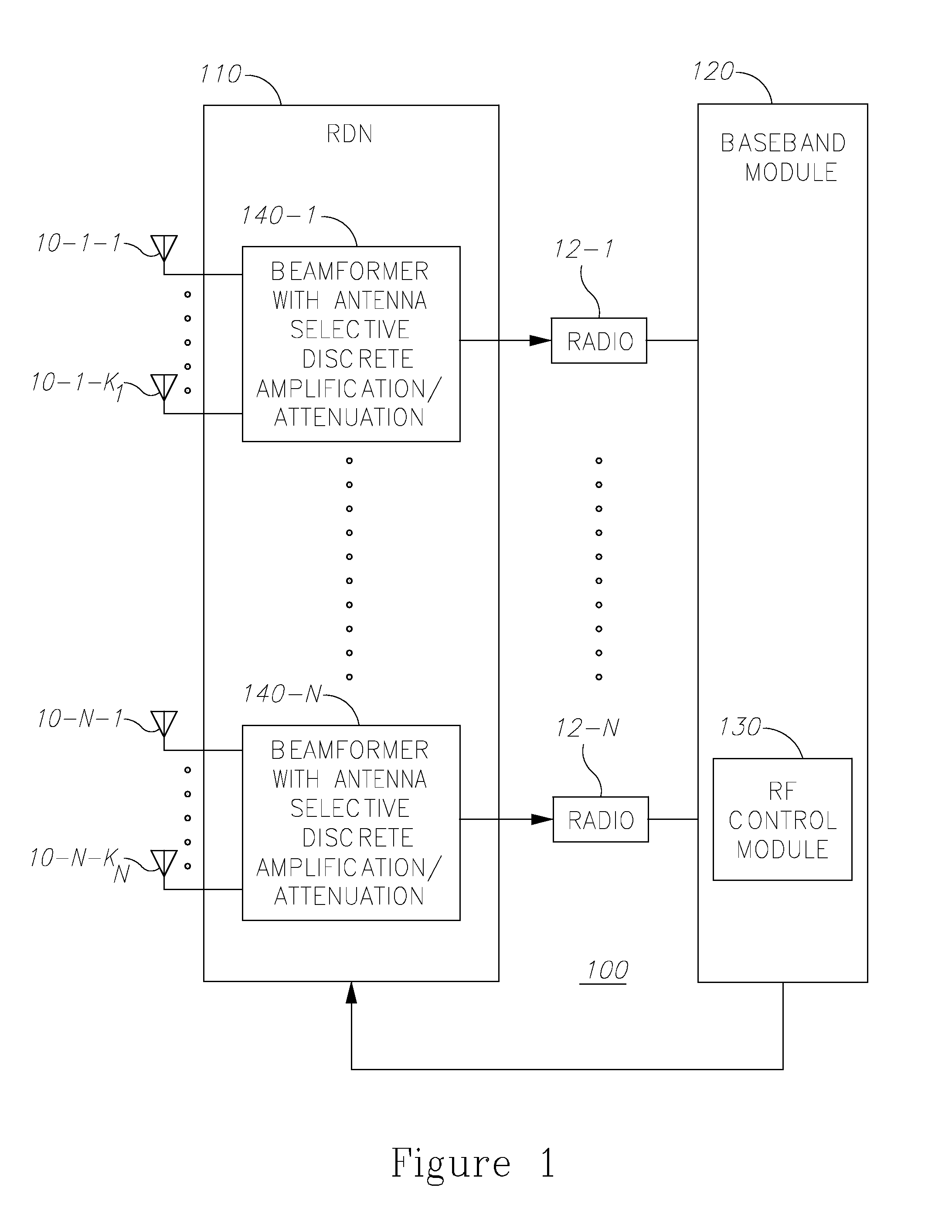
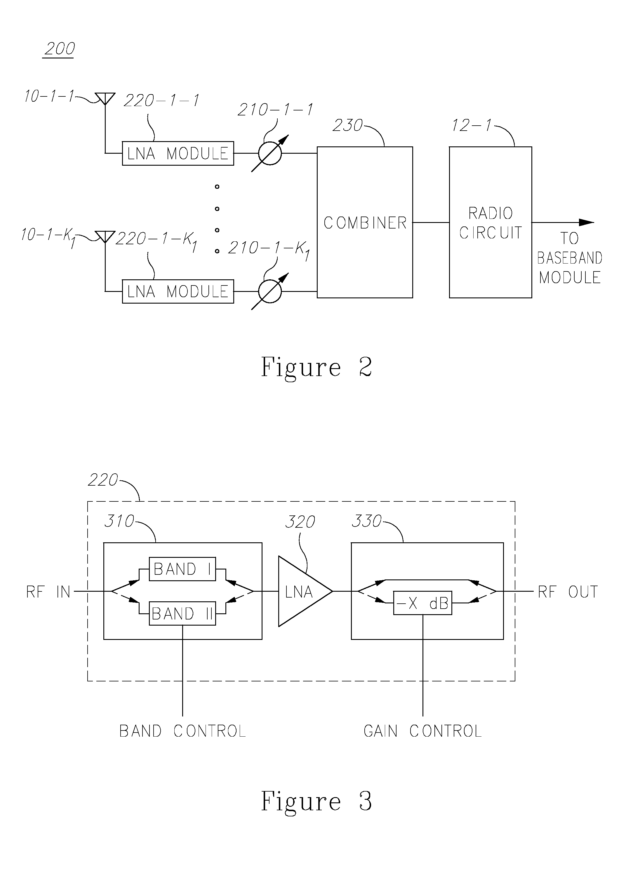
[0012]Some embodiments of the present invention include a system and method for selectively and discretely amplifying or attenuating antennas in a hybrid multiple-input-multiple-output (MIMO) radio distribution network (RDN) receiving system. The system may include a MIMO receiving system including a MIMO baseband module having N branches; an RDN connected to the MIMO receiving system, the RDN comprised of at least one beamformer fed by (e.g., receives input from) two or more antennas, so that a total number of antennas in the system is M, wherein M is greater than N, wherein each one of the beamformers include a passive combiner configured to combine signals coming or received from the antennas coupled to a respective beamformer into a combined signal, wherein the at least one beamformer is further configured to selectively amplify or attenuate in discrete values, one or more of the signals coming from the M antennas, based on one or more quality metrics measured by the MIMO baseband module.

Problems solved by technology

This is achieved by combining elements in the array in such a way that signals at particular angles experience constructive interference while others experience destructive interference.
A drawback of passive combining schemes is that if the input signals or noises have different powers, theses imbalances may significantly affect the SINR of the combined signal at the output of the combiner of the beamformer and may therefore degrade the gain of the beamformer.

Method used


Image

  • System and method for discrete gain control in hybrid MIMO RF beamforming for multi layer MIMO base station
  • System and method for discrete gain control in hybrid MIMO RF beamforming for multi layer MIMO base station
  • System and method for discrete gain control in hybrid MIMO RF beamforming for multi layer MIMO base station

Examples


Embodiment Construction

[0024]With specific reference now to the drawings in detail, it is stressed that the particulars shown are for the purpose of example and solely for discussing the preferred embodiments of the present invention, and are presented in the cause of providing what is believed to be the most useful and readily understood description of the principles and conceptual aspects of the invention. In this regard, no attempt is made to show structural details of the invention in more detail than is necessary for a fundamental understanding of the invention. The description taken with the drawings makes apparent to those skilled in the art how the several forms of the invention may be embodied in practice.

[0025]It is to be understood that the invention is not limited in its application to the details of construction and the arrangement of the components set forth in the following descriptions or illustrated in the drawings. The invention is applicable to other embodiments and may be practiced or ...


PUM


Abstract

A multiple-input-multiple-output (MIMO) receiving system configured for receiving multiple transmission layers is provided herein. The system includes a plurality of beamformed tunable receiving antennas configured to receive a plurality of transmitted layers; and a control module configured to select for the beamformed antennas a single set of discrete weights for tuning said antennas for all of the transmitted layers so that the weights are selected for optimal performance of said receiving system, wherein said selection is carried out based on an extended Maximal Ratio Combining (MRC) metric or other quality metric measured by the MIMO baseband module, and using said measured metric separately for each beamformed antenna to determine gain or attenuation independently of phase selection.

Description

CROSS-REFERENCE TO RELATED APPLICATIONS[0001]This application is a continuation-in-part application of U.S. patent application Ser. No. 13 / 762,188, filed on Feb. 7, 2013, which is a continuation-in-part application of U.S. patent application Ser. No. 13 / 630,146 filed on Sep. 28, 2012, which claims benefit from U.S. Provisional Patent Application Nos.: 61 / 652,743 filed on May 29, 2012; 61 / 657,999 filed on Jun. 11, 2012; and 61 / 665,592 filed on Jun. 28, 2012; U.S. patent application Ser. No. 13 / 762,188 also claims benefit from U.S. Provisional Patent Application Nos.: 61 / 658,015 filed on Jun. 11, 2012; 61 / 658,001 filed on Jun. 11, 2012; 61 / 658,004 filed on Jun. 11, 2012; 61 / 665,590 filed on Jun. 28, 2012; 61 / 667,053 filed on Jul. 2, 2012; and 61 / 665,605 filed on Jun. 28, 2012, all of which are incorporated by reference herein in their entirety.FIELD OF THE INVENTION[0002]The present invention relates generally to the field of radio frequency (RF) multiple-input-multiple-output (MIMO) ...

Claims


Application Information

Patent Timeline
Patent Type & Authority Applications(United States)
IPC IPC(8): H03G3/20H04B7/08
CPCH04B7/0842H03G3/20H04B7/0413H04B7/086H04B7/0857
Inventor KLUDT, KENNETHABREU, EDUARDOHAREL, HAIM
Owner MAGNOLIA BROADLAND INC
Why Eureka
Try Eureka