Electronic control device

Active Publication Date: 2014-03-20
HITACHI ASTEMO LTD
View PDF5 Cites 27 Cited by
  • Summary
  • Abstract
  • Description
  • Claims
  • Application Information

AI Technical Summary

Benefits of technology

[0022]In the electronic control device according to the third aspect of the present invention, a seal length of the connector-side waterproof seal portion becomes a sum of a width of the connector-side waterproof seal portion and an amount of projection of the barrier portion which projects from the connector toward the one of the pair of ho

Problems solved by technology

In addition, in the above-described latter conventional art as shown in FIGS. 12A-12B, removal of the disposal board leads to r

Method used


Image

  • Electronic control device
  • Electronic control device
  • Electronic control device

Examples


Example

First Embodiment

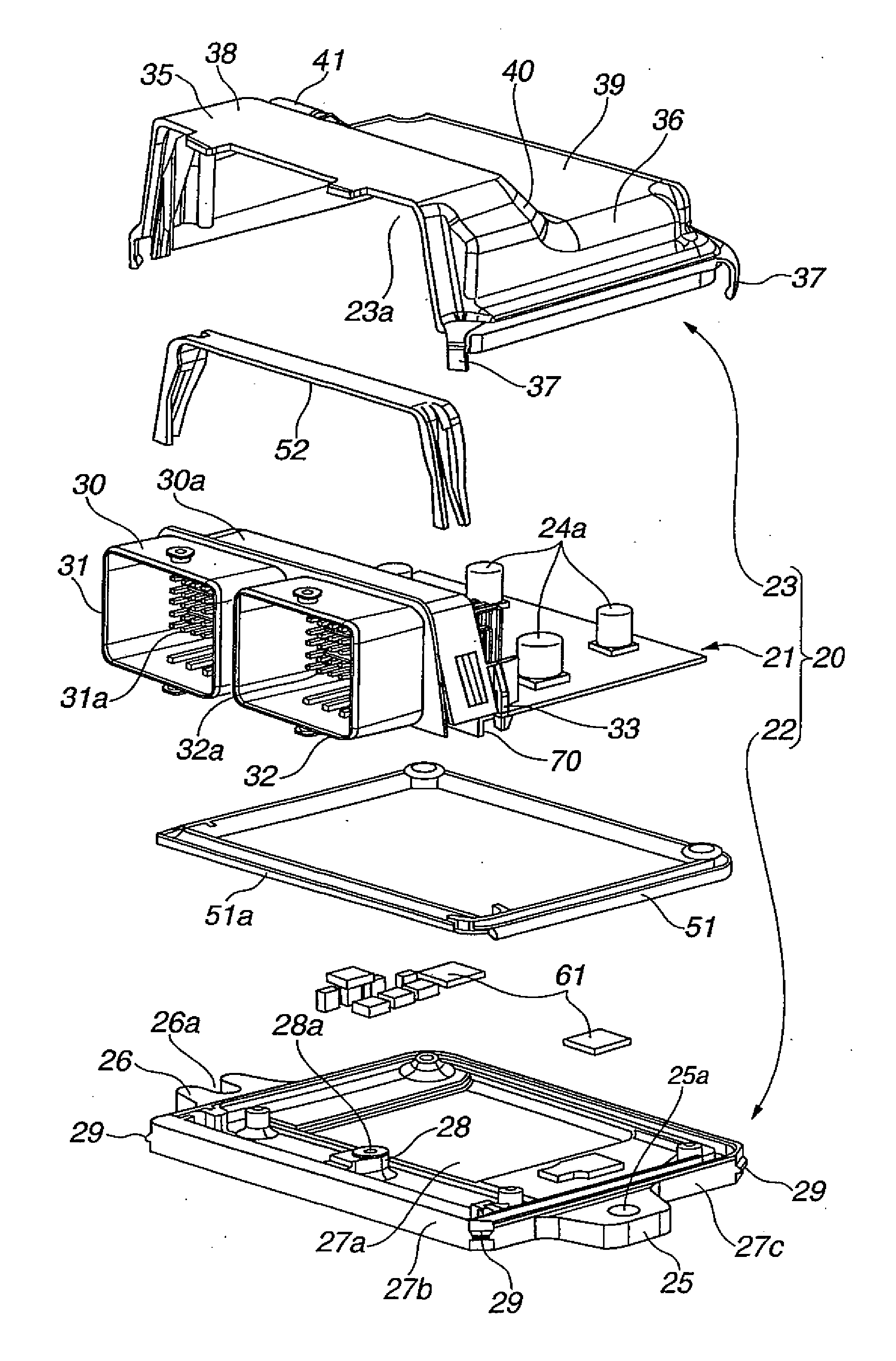
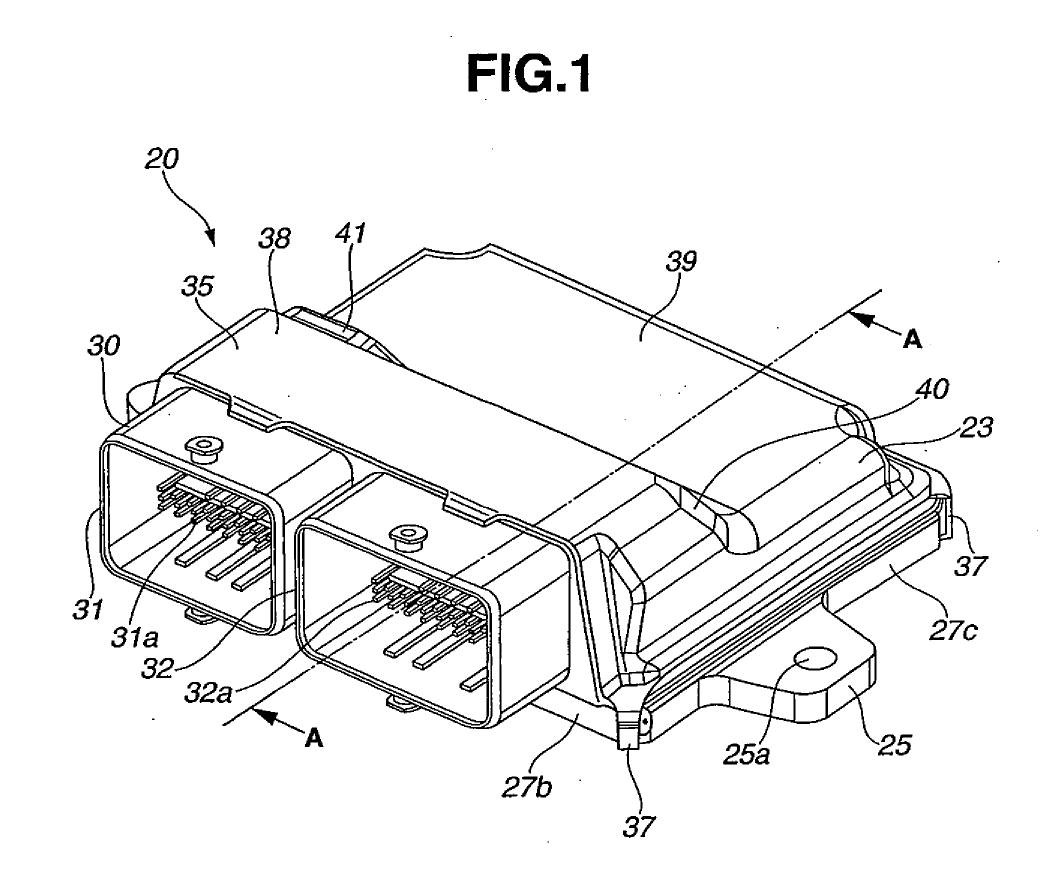
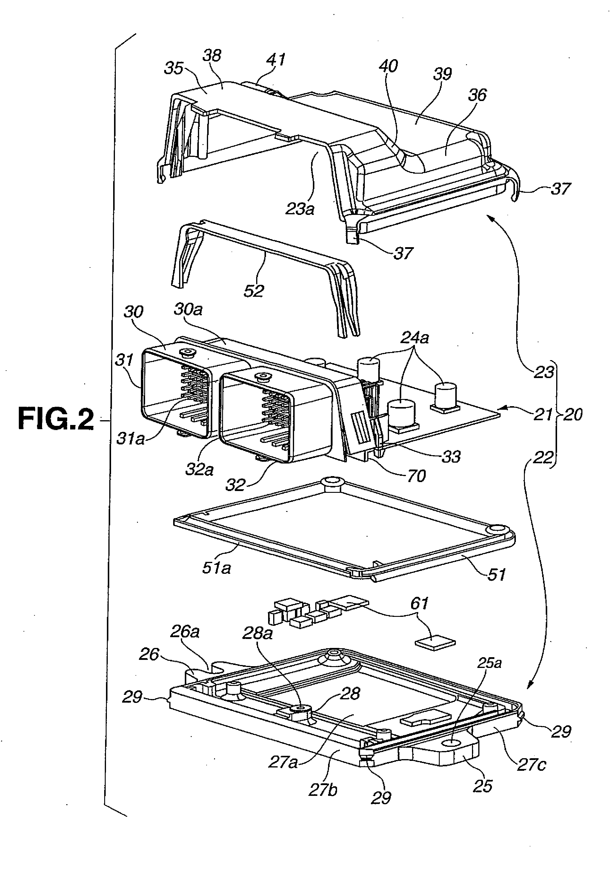
[0044]Referring to FIG. 1 to FIG. 6C, a basic construction of the electronic control device of the first embodiment is explained. In the basic construction of the first embodiment, electronic control device 20 includes a pair of housing members (case 22 and cover 23 as explained later) which cooperate to form a housing, and circuit board 21 accommodated in an inside space within the housing. In the following explanation, the expression “vertical direction” of electronic control device 20 as shown in FIG. 1 to FIG. 3, that is, a thickness direction of circuit board 21 may be used as a vertical direction of electronic control device 20 itself. However, the vertical direction of electronic control device 20 itself does not always correspond to a vertical direction of the vehicle. In a case where electronic control device 20 is mounted to the vehicle in an upright attitude, the vertical direction of electronic control device 20 as shown in FIG. 1 extends along a forward-...

Example

Second Embodiment

[0073]Referring to FIG. 8A and FIG. 8B, barrier portion 70 used in electronic control device 120 according to a second embodiment will be explained. The second embodiment differs from the first embodiment in configuration of barrier portion 70. Like reference numerals denote like parts, and therefore, detailed explanations therefor are omitted. As shown in FIG. 8B, barrier portion 70 includes tapered portion 70a tapered toward a tip end of barrier portion 70 which is opposed to the upper surface of bottom wall 27a of case 22.

[0074]With the provision of tapered portion 70a of barrier portion 70, an application nozzle for applying the flux and the coating agent to the board connecting portions of connector pins 31a, 32a can be prevented from contacting barrier portion 70. Further, it is possible to facilitate molding of barrier portion 70.

Example

Third Embodiment

[0075]Referring to FIG. 9A and FIG. 9B, barrier portion 70 used in electronic control device 220 according to a third embodiment will be explained. The third embodiment differs from the second embodiment in configuration of tapered portion 70a of barrier portion 70. Like reference numerals denote like parts, and therefore, detailed explanations therefor are omitted. As shown in FIG. 9A and FIG. 9B, tapered portion 70a of barrier portion 70 includes rounded tip end portion 70b.

[0076]With this construction in which barrier portion 70 has a tapered portion with rounded tip end portion 70b, it is possible to more effectively prevent the application nozzle for applying the flux and the coating agent to the board connecting portions of connector pins 31a, 32a from contacting barrier portion 70. In addition, it is possible to further facilitate molding of barrier portion 70.


PUM


Abstract

An electronic control device including a circuit board, a connector with connector pins having a board connecting portion at which the connector pins are electrically connected with the circuit board, a pair of housing members accommodating the circuit board and the connector therebetween, a waterproof seal portion through which connection between the connector and the pair of housing members and connection between the pair of housing members are provided in a fluid-tight manner, the waterproof seal portion including a connector-side waterproof seal portion disposed between the connector and one of the pair of housing members which is opposed to the board connecting portion of the connector pins, and a barrier portion disposed between the board connecting portion of the connector pins and the connector-side waterproof seal portion.

Description

BACKGROUND OF THE INVENTION[0001]The present invention relates to an electronic control device for a vehicle which includes a circuit board accommodated in a protection space within a housing.[0002]A generally known electronic control device such as an engine control unit, a control unit for an automatic transmission, etc. which is installed in a vehicle, includes a housing formed by a pair of housing members joined with each other, and a circuit board accommodated in a protection space (for instance, a waterproof space) within the housing. The circuit board is equipped with electronic parts mounted thereto and a connector attached thereto.[0003]A so-called connector horizontal exit electronic control device in which a portion of a connector attached to the circuit board is exposed outside through a window provided on a side face of the housing includes a waterproof seal portion formed on a connecting portion between the connector and the pair of housing members. The waterproof seal...

Claims


Application Information

Patent Timeline
IPC IPC(8): H01R13/52
CPCH01R13/5202H05K5/0069H05K7/14
Inventor YAMANAKA, KENTAROOHHASHI, HIRONORIKAWAI, YOSHIO
Owner HITACHI ASTEMO LTD
Why Eureka
Try Eureka