

Assembled damping hammer
- Summary
- Abstract
- Description
- Claims
- Application Information
AI Technical Summary
Benefits of technology
Problems solved by technology
Method used
Image

Examples
Embodiment Construction
[0012]However, it shall be appreciated by those of ordinary skill in the art that, the detailed description and specific embodiments enumerated for implementation of the present invention are only intended to illustrate the present invention but not to limit the scope of the present invention.
BRIEF DESCRIPTION OF THE SEVERAL VIEWS OF THE DRAWINGS
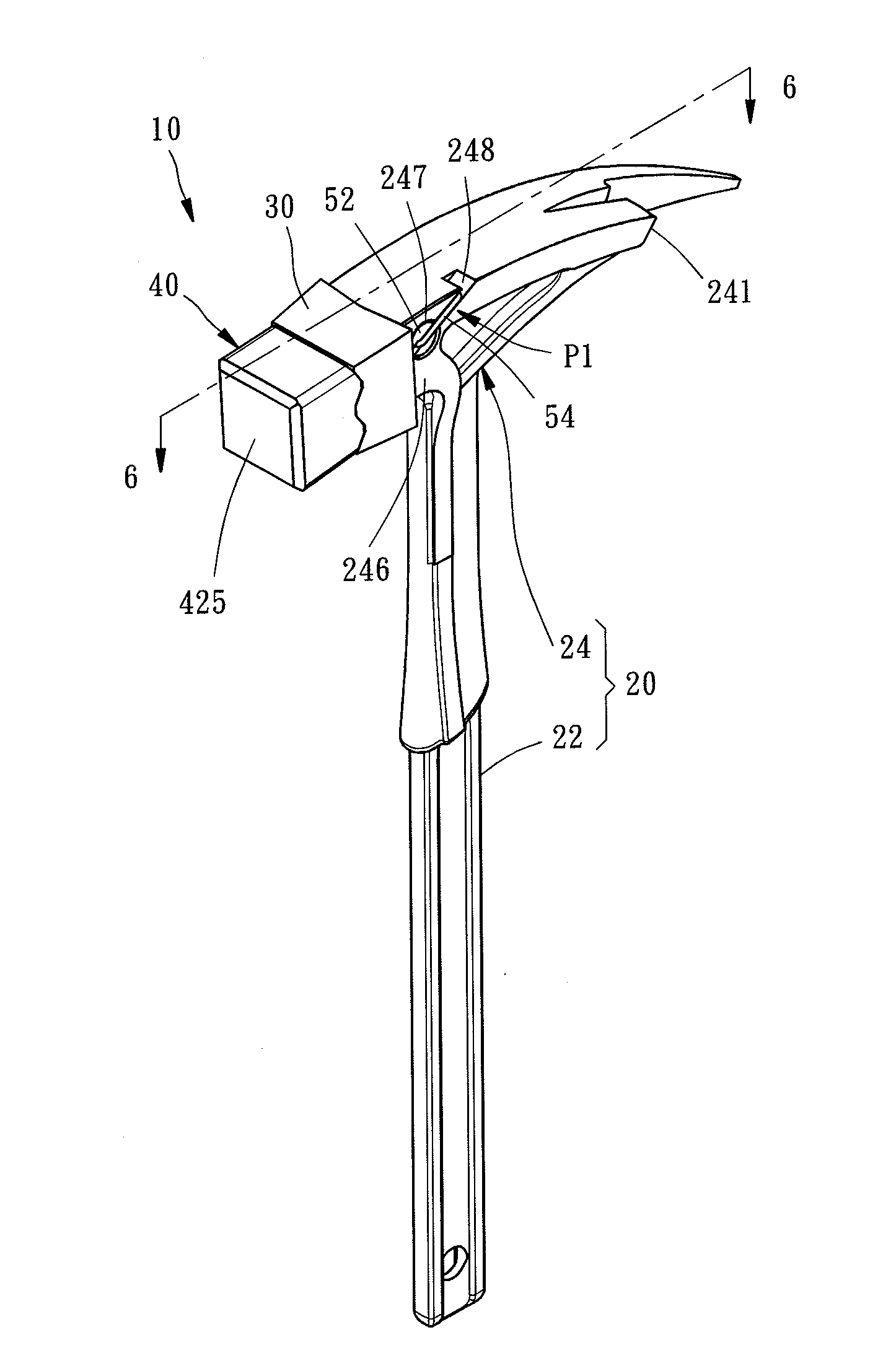
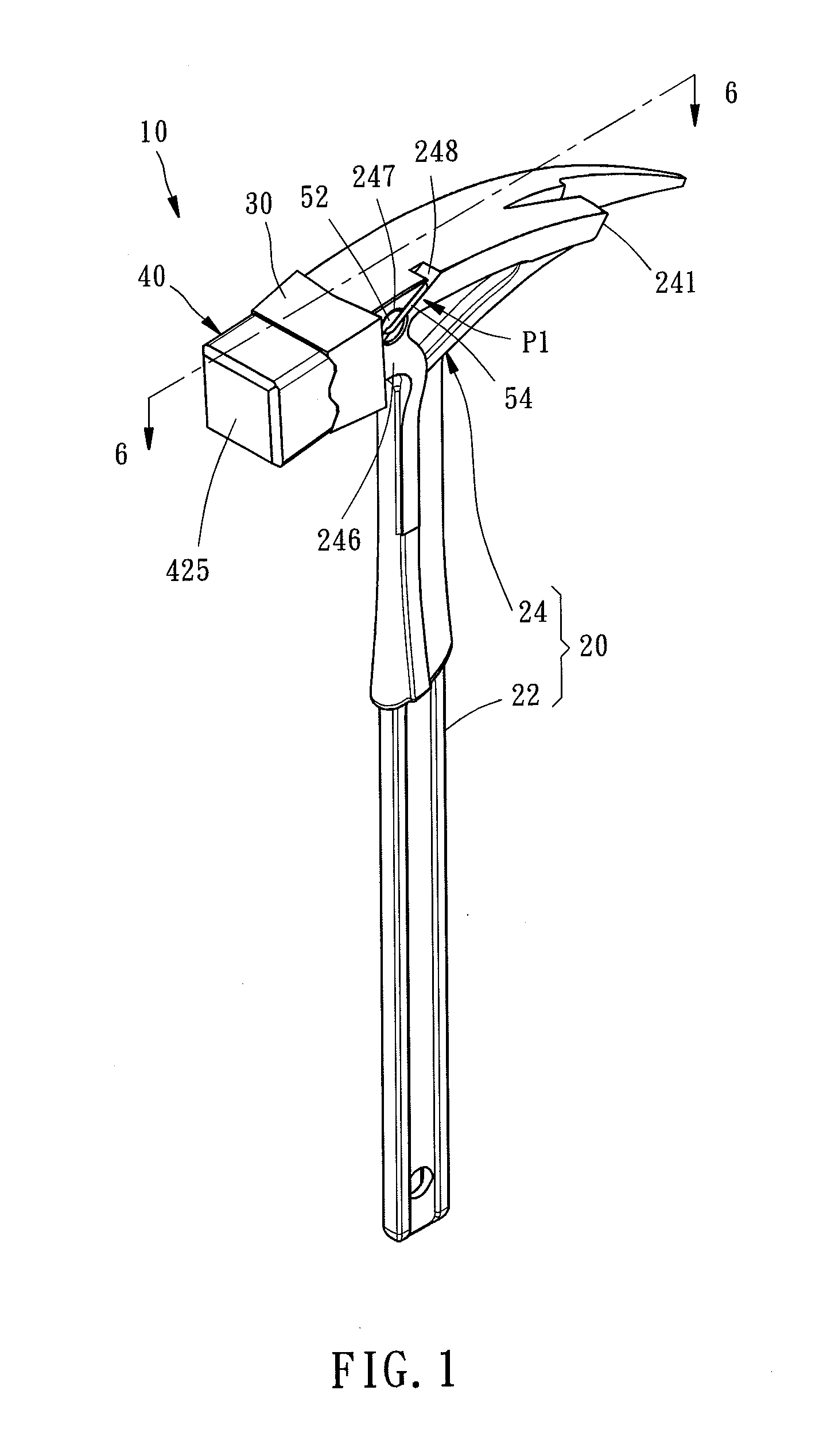
[0013]FIG. 1 is a perspective assembly view of an assembled damping hammer according to a first preferred embodiment of the present invention;
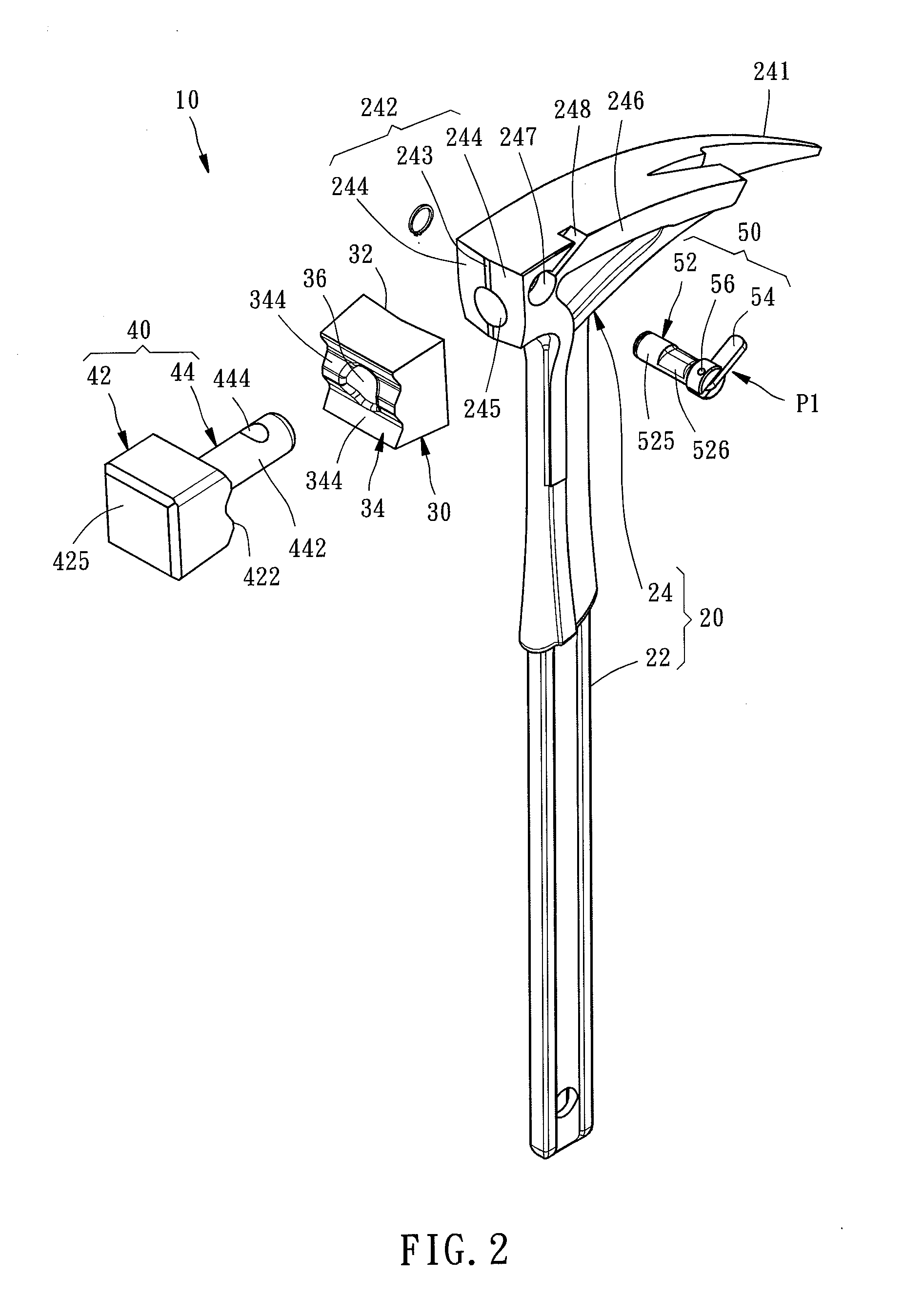
[0014]FIG. 2 and FIG. 3 are perspective exploded views of the assembled damping hammer according to the first preferred embodiment of the present invention;
[0015]FIG. 4 is a perspective view of a damping block of the assembled damping hammer according to the first preferred embodiment of the present invention;
[0016]FIG. 5 is a perspective view of a working piece of the assembled damping hammer according to the first preferred embodiment of the present invention;
[0017]FIG. 6 is a cross-sectional view of...
PUM
| Property | Measurement | Unit |
|---|---|---|
| Strength | aaaaa | aaaaa |
Abstract
Description
Claims
Application Information