Vibration-reducing structure for four-compression-chamber diaphragm pump

Inactive Publication Date: 2015-11-26
CAI YING LIN +1
View PDF36 Cites 5 Cited by
  • Summary
  • Abstract
  • Description
  • Claims
  • Application Information

AI Technical Summary

Benefits of technology

[0024]An objective of the present invention is to provide a vibration-reducing structure for four-compressing-chamber diaphragm pump features of a pump head body and a diaphragm membrane, in which the pump head body includes four operating holes and at least one basic curved groove, slot, or perforated segment, or a curved protrusion or set of protrusions, circumferentially disposed around at least a portion of the upper side of each operating hole, and in which the diaphragm membrane includes four equivalent piston acting zones each of which has an acting zone hole, an annular positioning protrusion for each acting zone hole, and at least one basic curved protrusion or set of protrusions, or a groove, slot, or perforated segment, at least partially circumferentially disposed around each concentric annular positioning protrusion at a position corresponding to the position of each mating basic curved groove, slot, perforated segment, protrusions, or sets of protrusions in the pump head body, so that the four basic curved protrusions, sets of protrusions, grooves, slots, or perforated segments are completely inserted into or received by the corresponding four basic curved grooves, slots, perforated segments, protrusions, or sets of protrusions in the pump head body with a short length of moment arm to generate less torque, the torque being obtained by multip

Problems solved by technology

Referring to FIGS. 12 through 13, a serious vibration-related drawback has long existed in the above-described conventional four-compression-chamber diaphragm pump.
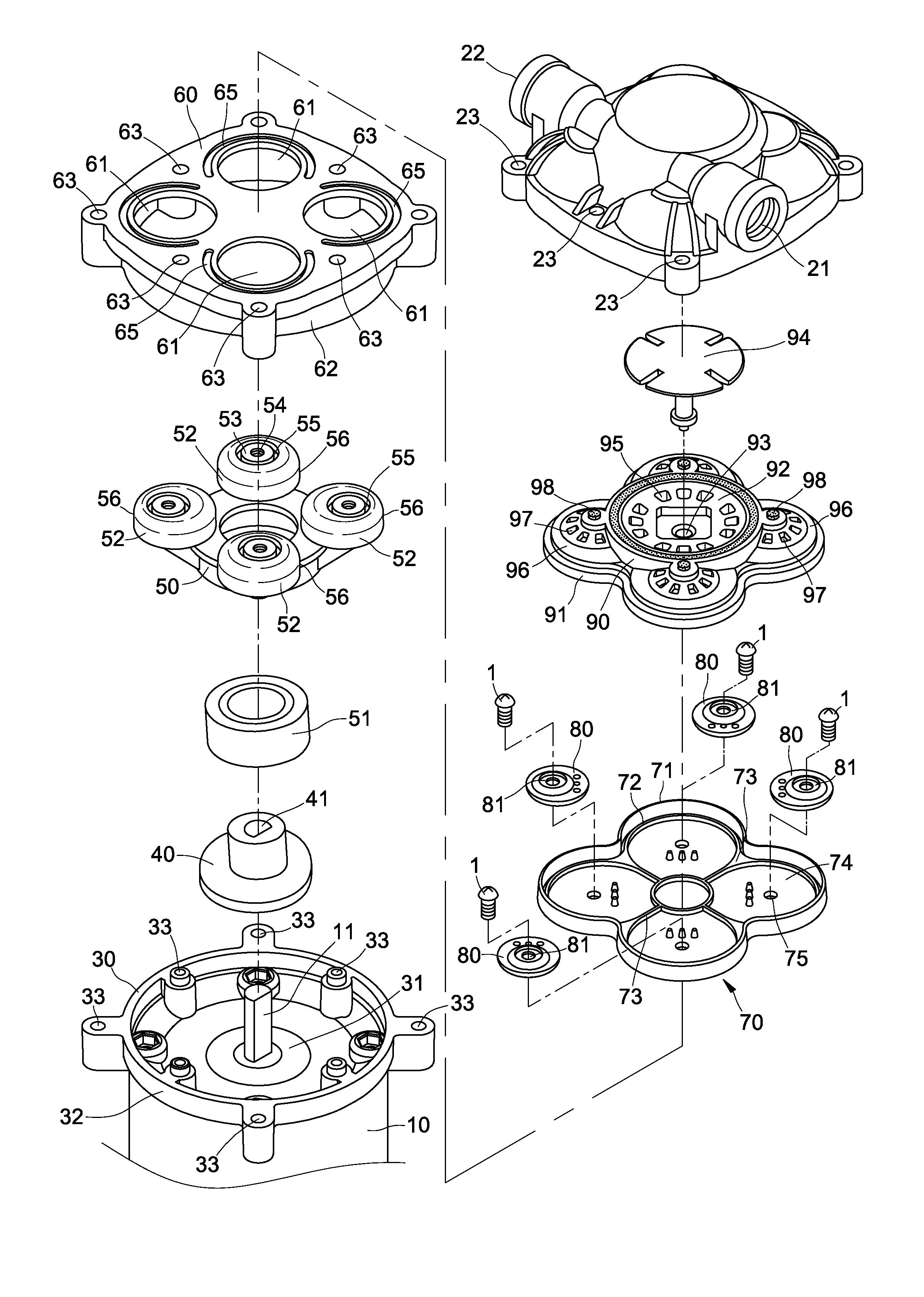
However, the practical vibration suppressing efficiency of the foregoing cushion base 100 with wing plates 101 and rubber shock absorber 102 only affects the primary direct vibration, while reducing overall vibration only to a limited degree because the primary direct vibration causes a secondary vibration to occur as a result of resonant shaking of the housing C. The resonant shaking causes the overall vibration noise of the housing C of the reverse osmosis purification unit to become stronger.
In addition to the drawback of increasing overall vibration noise of the housing C, a further drawback occurs in that the water pipe P connected to the water outlet orifice 22 of the pump head cover 20 will synchronously shake in resonance with the primary vibration described above (

Method used


Image

  • Vibration-reducing structure for four-compression-chamber diaphragm pump
  • Vibration-reducing structure for four-compression-chamber diaphragm pump
  • Vibration-reducing structure for four-compression-chamber diaphragm pump

Examples


Example

[0144]As shown in FIGS. 36 and 37, in the second exemplary embodiment, each linked four-curve groove 68 in the pump head body 60 can be replaced by a linked four-curve slot 641.

[0145]Alternatively, as shown in FIGS. 38 and 39, the linked four-curve groove 68 in the pump head body 60 of the second exemplary embodiment (as shown in FIGS. 29 to 31) and the corresponding linked four-curve protrusion 79 in the diaphragm membrane 70 (as shown in FIGS. 33 and 34) can be replaced by a linked four-curve protrusion 681 in the pump head body 60 (as shown in FIG. 38) and a linked four-curve groove 791 in the diaphragm membrane 70 (as shown in FIG. 38) without affecting their mating condition.

[0146]Thereby, the linked four-curve protrusion 681 at the upper side of the pump head body 60 may be completely inserted into the linked four-curve groove 791 in the bottom side of the diaphragm membrane 70 upon assembly of the pump head body 60 and the diaphragm membrane 70 (as shown in FIG. 39) to achiev...

Example

[0151]As shown in FIGS. 47 and 48, in the third exemplary embodiment, each pair of basic curved groove 65 and second outer curved groove 66 of the pump head body 60 can be replaced by a pair of bores including a basic curved bore 64 and second outer curved bore 67.

[0152]Alternatively, as shown in FIGS. 49 and 50, in the third exemplary embodiment, each pair of basic curved groove 65 and second outer curved groove 66 in the pump head body 60 (as shown in FIGS. 40 to 42) and each corresponding pair of basic curved protrusion 77 and second outer curved protrusion 78 in the diaphragm membrane 70 (as shown in FIGS. 44 and 45) can be respectively exchanged for a pair of basic curved protrusion 651 and second outer curved protrusion 661 in the pump head body 60 (as shown in FIG. 49) and a pair of corresponding basic curved groove 771 and second outer curved groove 781 in the diaphragm membrane 70 (as shown in FIG. 49) without affecting their mating condition.

[0153]Thereby, each pair of bas...

Example

[0165]As shown in FIGS. 69 and 70, in the fifth exemplary embodiment, each group of curved grooves 602 of the pump head body 60 can be replaced by a group of curved slits 611.

[0166]As shown in FIGS. 71 and 72, in the fifth exemplary embodiment, each group of curved grooves 602 in the pump head body 60 (as shown in FIGS. 62 to 64) and each corresponding group of curved protrusions 702 in the diaphragm membrane 70 (as shown in FIGS. 66 and 67) can be respectively exchanged for a group of curved protrusions 620 in the pump head body 60 (as shown in FIG. 71) and a group of corresponding curved grooves 720 in the diaphragm membrane 70 (as shown in FIG. 71) without affecting their mating condition.

[0167]Each group of curved protrusions 620 at the upper side of the pump head body 60 is completely inserted into each group of corresponding curved grooves 720 at the bottom side of the diaphragm membrane 70 upon assembly of the pump head body 60 and the diaphragm membrane 70 (as shown in FIG. ...


PUM


Abstract

A vibration-reducing structure for compressing diaphragm pump features a pump head body and a diaphragm membrane. The pump head body includes four operating holes, a first curved vibration-reducing positioning structure circumferentially disposed around the upper side of each operating hole, and or a linked four-curve positioning structure that collectively extends around all of the operating holes. The diaphragm membrane includes four equivalent piston acting zones and second curved vibration-reducing position structures situated at positions corresponding to the positions of the first curved vibration-reducing positioning structures. The first positioning structures in the pump head body, which may be grooves, slots, perforations, or protrusions, mate with the corresponding second positioning structures in the diaphragm membrane to reduce the moment arm generated during pumping by movement of the diaphragm membrane, which may be protrusions, grooves, slots, or perforations, thereby generating less torque to decrease the strength of vibrations and vibration noise.

Description

[0001]This application claims the benefit of provisional U.S. Patent Application No. 61 / 000,622, filed May 20, 2014, and incorporated herein by reference.FIELD OF THE PRESENT INVENTION[0002]The present invention relates to a vibration-reducing structure for a four-compression-chamber diaphragm pump, and particularly to a structure that can reduce the vibration strength of the pump so that the annoying noise incurred by the consonant vibration with the housing of an RO purification system is eliminated when the vibration-reducing structure is installed on the water supplying apparatus in either a house, recreational vehicle, or mobile home.BACKGROUND OF THE INVENTION[0003]Conventional compressing diaphragm pumps of the type used with a RO (Reverse Osmosis) purifier or RO water purification system, and which are popularly installed on the water supplying apparatus of houses, recreational vehicles or mobile homes, come in various types. Other than the specific type disclosed in U.S. Pa...

Claims


Application Information

Patent Timeline
IPC IPC(8): F04B53/00F04B17/03F04B53/16F04B45/047F04B53/10F04B3/00F04B53/14
CPCF04B53/003F04B3/00F04B17/03F04B53/16F04B45/047F04B53/10F04B53/14F04B43/0054F04B43/021F04B43/14F04B53/001
Inventor CAI, YING LINHSU, CHAO FOU
Owner CAI YING LIN
Why Eureka
Try Eureka