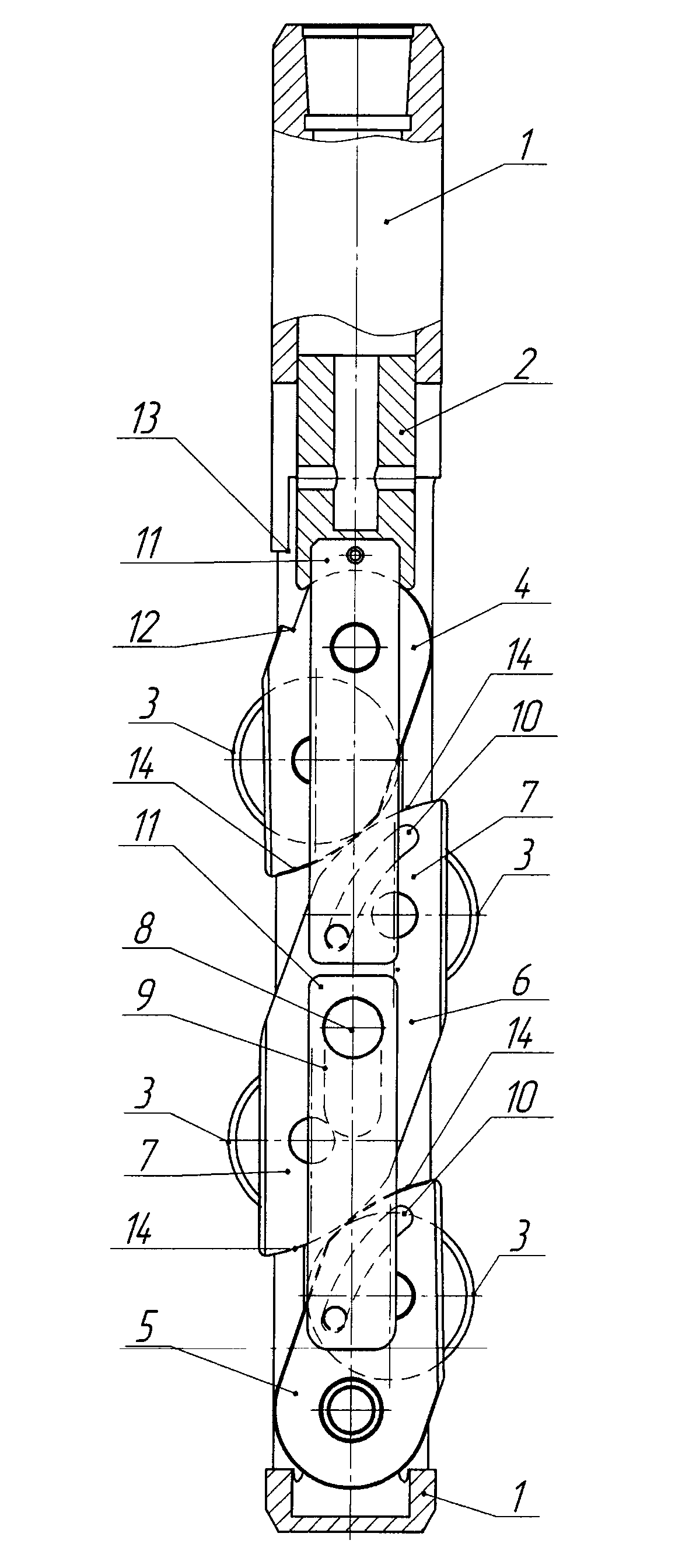
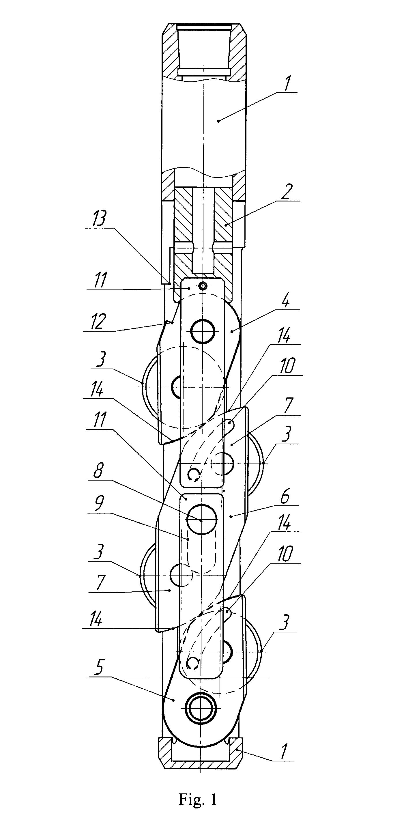
Cutting unit of a slot perforator (variants)

Active Publication Date: 2014-03-27
KUZYAEV SALAVAT ANATOLYEVICH MR
View PDF2 Cites 4 Cited by
  • Summary
  • Abstract
  • Description
  • Claims
  • Application Information

AI Technical Summary

Benefits of technology

The invention proposes a new design for a cutting unit used in a perforator. The new design increases the speed of cutting and reduces wear and tear on the cutting tools. It also provides a uniform quality and sufficient depth of perforating slots, improves the reliability of the perforator, and extends the use of cutting tools. The cutting units can be equipped with additional cutting tools to increase productivity. The cutting units are smaller and more efficient, resulting in a sufficient depth of the cut of perforating slots. The presence of a retractable mechanism improves safety and a rounded surface on the wedge-type parts prevents jamming and ensures a continuous force during the extension process. The technical effects of the invention include increased productivity, improved performance, and better reliability of the perforator.

Problems solved by technology

However, the disadvantage of multiple-cutting units is the application of cutting tools extension mechanisms, suggesting the presence of a significant distance between the cutting tools in working position.
However, the large distance between the cutting tools will lead to the fact that they will work on segments of the perforation interval, only partially overlapping, so the segments of perforating slots formed at the same time will have a significant height difference.
This will lead to uneven opening of the column and to uneven wear of cutting tools, as well as to the possibility of unwanted disclosure of the column outside of the perforation interval.
In addition, the utilization of the known extension mechanisms of cutting tools in multi-sectional cutter units, especially those where the section contains only one cutting tool, results in increase of perforators size, making them too long, cumbersome, affects the performance of the perforators.
The above drawbacks complicate the use of perforators with multi-sectional cutting units for the purpose of acceleration of perforating slots formation.
The disadvantage of the cutting unit according to the prototype is the possibility of the inclusion of only two cutting disks—one disk for each of two projections of the perforation slots forming that does not accelerate opening of the column.
The lack of a mechanism to bring the cutting unit in the transport position and fix it in this position before and after perforation can also be attributed to the disadvantages of the prototype.

Method used


Image

  • Cutting unit of a slot perforator (variants)
  • Cutting unit of a slot perforator (variants)

Examples


Embodiment Construction

[0029]While the invention may be susceptible to embodiment in different forms, there are shown in the drawing, and will be described in detail herein, specific embodiments of the present invention, with the understanding that the present disclosure is to be considered an exemplification of the principles of the invention, and is not intended to limit the invention to that as illustrated and described herein.

[0030]Referring to the drawing, the inventive cutting unit is incorporated into a slot-type perforator comprising: a casing 1 having a specific edge 13, and a piston 2 movable within the casing 1; the cutting unit is mounted in the casing 1, and is associated with and driven by the piston 2; the cutting unit includes telescoping cutting tools 3 with a mechanism of their extension accomplished in the form of holders 4, 5, one of which 4 is fixed with the respect to the piston 2 and the other 5 is fixed with the respect to the casing 1. The holders 4 and 5 are executed with the abi...


PUM


Abstract

A cutting unit for a slot-type perforator is mounted in a casing, driven by a pusher, containing cutting tools with an extension mechanism for extending thereof, including a holder fixed to the pusher and another holder fixed to the casing. The holders are capable of rotating, causing an extension and retraction of the cutting tools from and to the casing. The extension mechanism includes a balance beam, having shoulders for placing the cutting tools and being assembled in the casing between the holders. The beam rotates around an axle during interaction with the holders. The axle is adapted to move along the longitudinal axis of the casing, e.g. in a groove arranged therein. The cutting unit may include at least two balance beams sequentially mounted between the holders. The cutting unit can be equipped with a retractable mechanism bringing parts thereof into a transportation position and fixing them therein.

Description

CROSS-REFERENCE TO RELATED APPLICATIONS[0001]This application is a U.S. national stage application of a PCT application PCT / IB2012 / 000215 filed on 8 Feb. 2012, published as WO2012107824, whose disclosure is incorporated herein in its entirety by reference, which PCT application claims priority of a Russian Federation patent application RU2011106440 filed on 10 Feb. 2011.FIELD OF THE INVENTION[0002]The proposed invention relates to drilling and well operations, in particular to the design of devices for the opening of productive layers through a slot perforation, and may be used in the construction and repair of wells for various purposes.BACKGROUND OF THE INVENTION[0003]In the prior art are known the cutting units of hydro-mechanical slot perforating machines, which include cutting tools enabling to form simultaneously two perforation slots in the production string, with the mechanism of their extension, for example, disclosed in patents RU 2249678 C2, IPC E21B 43 / 112, 10.04.2005, R...

Claims


Application Information

Patent Timeline
IPC IPC(8): E21B43/112
CPCE21B43/112
Inventor PASVANDI, MARIE
Owner KUZYAEV SALAVAT ANATOLYEVICH MR
Why Eureka
Try Eureka