Supercharge Your Innovation With Domain-Expert AI Agents!

Commutator

a commutator and commutator technology, applied in the field of commutators, can solve the problems of a large number of steps in the manufacture of commutators, and achieve the effect of high engagement for

Inactive Publication Date: 2014-03-27
ASMO CO LTD
View PDF7 Cites 2 Cited by
  • Summary
  • Abstract
  • Description
  • Claims
  • Application Information

AI Technical Summary

Benefits of technology

The aim of this invention is to create a commutator that has a strong connection between its different parts and requires minimal steps in the manufacturing process.

Problems solved by technology

Hence, manufacture of the commutator involves a large number of steps.

Method used


Image

  • Commutator
  • Commutator
  • Commutator

Examples


first embodiment

[0035]A first embodiment according to the present invention will be described below based on FIGS. 1 to 7.

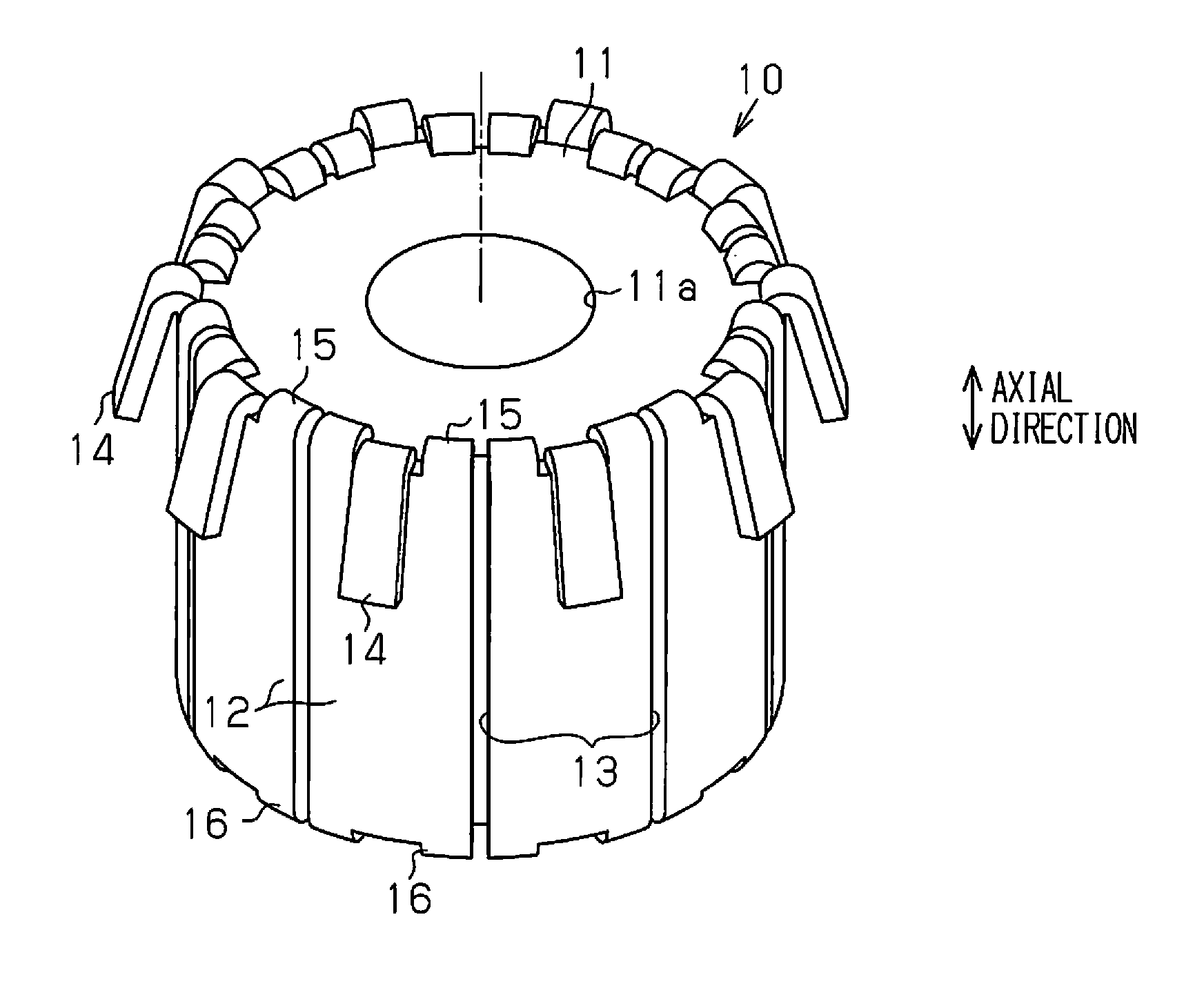
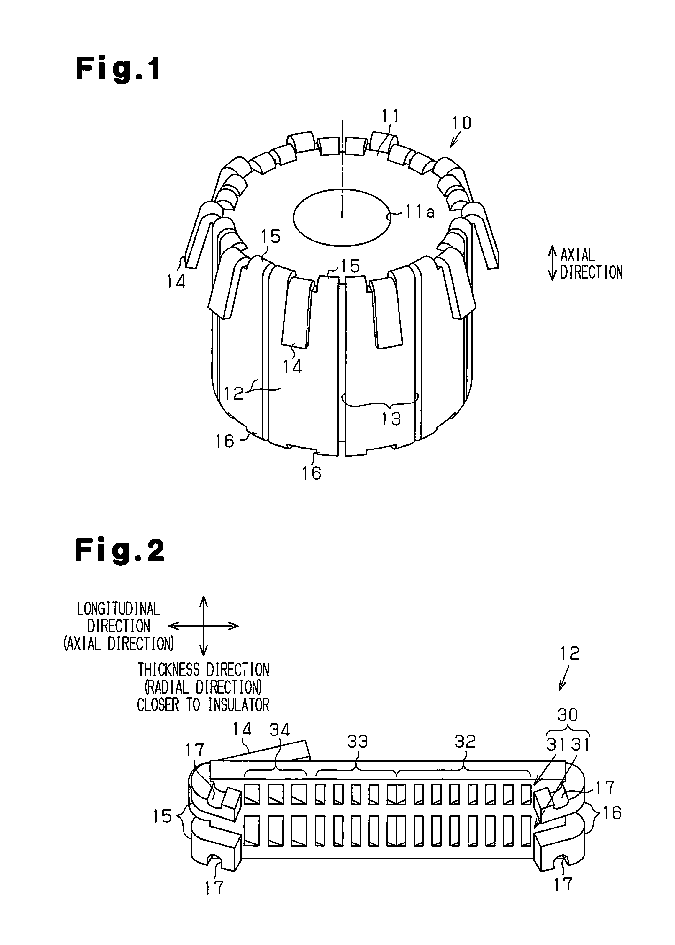
[0036]As shown in FIG. 1, a commutator 10 includes a cylindrical insulator 11 made of a thermosetting plastic, and ten segments 12 (commutator pieces) fixed to the outer circumferential surface of the insulator 11. A press-fitting hole 11a extending through the insulator 11 in the axial direction is formed at a radial central portion of the insulator 11. A rotary shaft of an armature (not shown) is press-fitted in the press-fitting hole 11a. Accordingly, the commutator 10 rotates integrally with the rotary shaft of the armature.

[0037]Each segment 12 is formed from a conductive plate material (for example, a metal plate such as a copper plate). The ten segments 12 are strips extending in the axial direction of the insulator 11 while being uniformly spaced angularly in the circumferential direction of the insulator 11. A partition groove 13 extending in the axial direction of the ...

second embodiment

[0061]A second embodiment of the commutator will now be described. The second embodiment mainly differs from the first embodiment in a first inner claw. Like or the same reference numerals are given to those components that are like or the same as the corresponding components of the first embodiment, and detailed explanations are omitted.

[0062]As shown in FIG. 10, a commutator 101 includes a cylindrical insulator 11, and eighteen segments 120 fixed to the outer circumferential surface of the insulator 11. The eighteen segments 120 are uniformly spaced angularly in the circumferential direction. The segments 120 each occupy an angle θ1 in the circumferential direction. Except for risers 14, second inner claws 16, and first inner claws 121, which will be described below, the eighteen segments 120 together have an inside diameter φ1 and an outer diameter φ2. Specifically, parts of the eighteen segments 120 excluding their risers 14, the second inner claws 16, and the first inner claws ...


PUM


Abstract

A commutator includes a cylindrical insulator and commutator pieces, which are formed on the outer circumferential surface of the insulator and arranged side by side in the circumferential direction of the insulator. The commutator pieces are each composed of a conductive plate material, and each includes a connection claw and an engagement claw. The connection claw extends outward in the radial direction of the insulator while being configured to electrically being connected to an armature coil. The engagement claw extends inward in the radial direction of the insulator and engages with the insulator. The commutator pieces each include a recess portion with an undercut formed in a surface facing inward in the radial direction of the insulator.

Description

BACKGROUND OF THE INVENTION[0001]The present invention relates to a commutator.[0002]A commutator for a DC motor includes a cylindrical insulator fixed to a rotary shaft of an armature, and multiple conductive segments attached to the outer circumferential surface of the insulator. Each segment has a riser connected to an end of a coil wound around a core of the armature. Feeding brushes are in sliding contact with the outer circumferential surfaces of the segments. The feeding brushes feed a direct current to the coil of the armature via the segments.[0003]The aforementioned commutator is manufactured as follows. A cylindrical conductive material is placed in a die and a plastic material is poured into the cylindrical material, thereby forming the aforementioned insulator. Then, the cylindrical material is cut along the axis to form the aforementioned segments.[0004]Japanese Laid-Open Patent Publication No. 2002-51506 discloses such a commutator. According to Japanese Laid-Open Pat...

Claims


Application Information

Patent Timeline
IPC IPC(8): H02K13/04
CPCH02K13/04H01R39/04H01R43/08H02K13/006
Inventor OSAWA, TOSHIYUKIHYOUDOU, KOUJIKAGEYAMA, RYOHEI
Owner ASMO CO LTD
Features
  • R&D
  • Intellectual Property
  • Life Sciences
  • Materials
  • Tech Scout
  • Unparalleled Data Quality
  • Higher Quality Content
  • 60% Fewer Hallucinations
Learn More