Illumination system and projection apparatus

a technology of projection apparatus and projection system, which is applied in the direction of lighting and heating apparatus, lighting support devices, instruments, etc., can solve the problems of limiting the life time of high-pressure mercury lamps, noise, and friction loss between shafts, and achieves the effect of reducing operation noise and prolonging life tim

Active Publication Date: 2014-03-27
CORETRONIC
View PDF18 Cites 11 Cited by
  • Summary
  • Abstract
  • Description
  • Claims
  • Application Information

AI Technical Summary

Benefits of technology

[0009]Accordingly, the invention is directed to an illumination system, and the illumination system is used in a projection apparatus to provide a longer life time and lower operation noise.

Problems solved by technology

The conventional projection apparatus generally uses a high-pressure mercury lamp as a light source (for example, an ultrahigh-pressure gas discharge lamp), though a large amount of emitted heat thereof limits a life time of the high-pressure mercury lamp.
However, a problem of friction loss is generated between a shaft and a bearing of the motor fan.
Usage of an oil-contained bearing may cause pollution, and a magnetic shearing sound caused by rotated motor fan and a wind shearing sound caused due to contact of rotated fan blades and air may all produce noise.

Method used


Image

  • Illumination system and projection apparatus
  • Illumination system and projection apparatus
  • Illumination system and projection apparatus

Examples


Embodiment Construction

[0023]In the following detailed description of the preferred embodiments, reference is made to the accompanying drawings which form a part hereof, and in which are shown by way of illustration specific embodiments in which the invention may be practiced. In this regard, directional terminology, such as “top,”“bottom,”“front,”“back,” etc., is used with reference to the orientation of the Figure(s) being described. The components of the present invention can be positioned in a number of different orientations. As such, the directional terminology is used for purposes of illustration and is in no way limiting. On the other hand, the drawings are only schematic and the sizes of components may be exaggerated for clarity. It is to be understood that other embodiments may be utilized and structural changes may be made without departing from the scope of the present invention. Also, it is to be understood that the phraseology and terminology used herein are for the purpose of description an...


PUM


Abstract

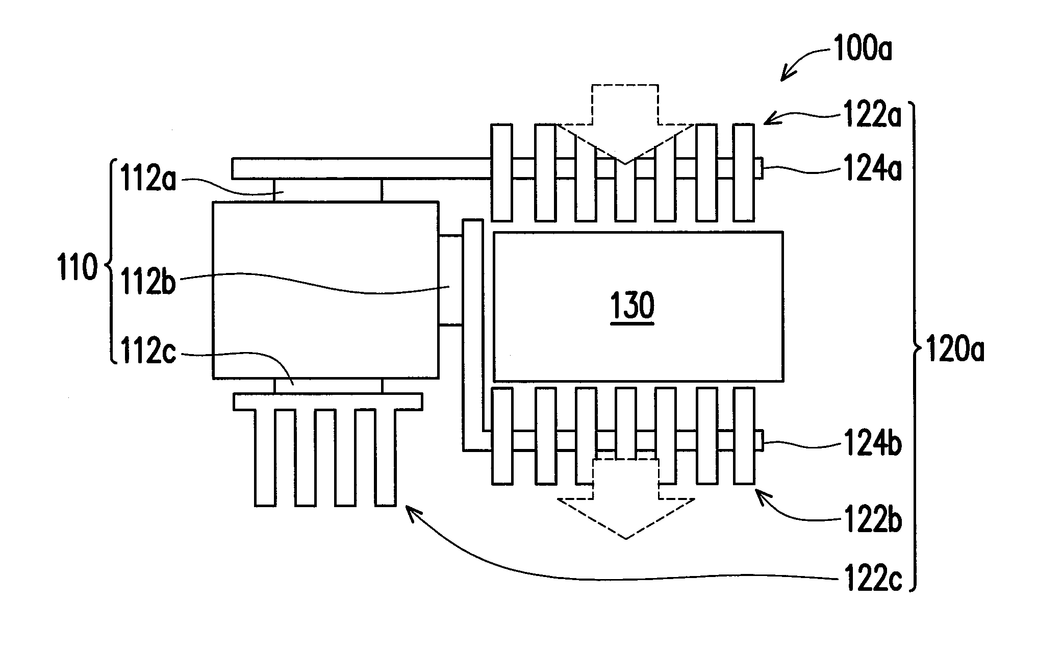
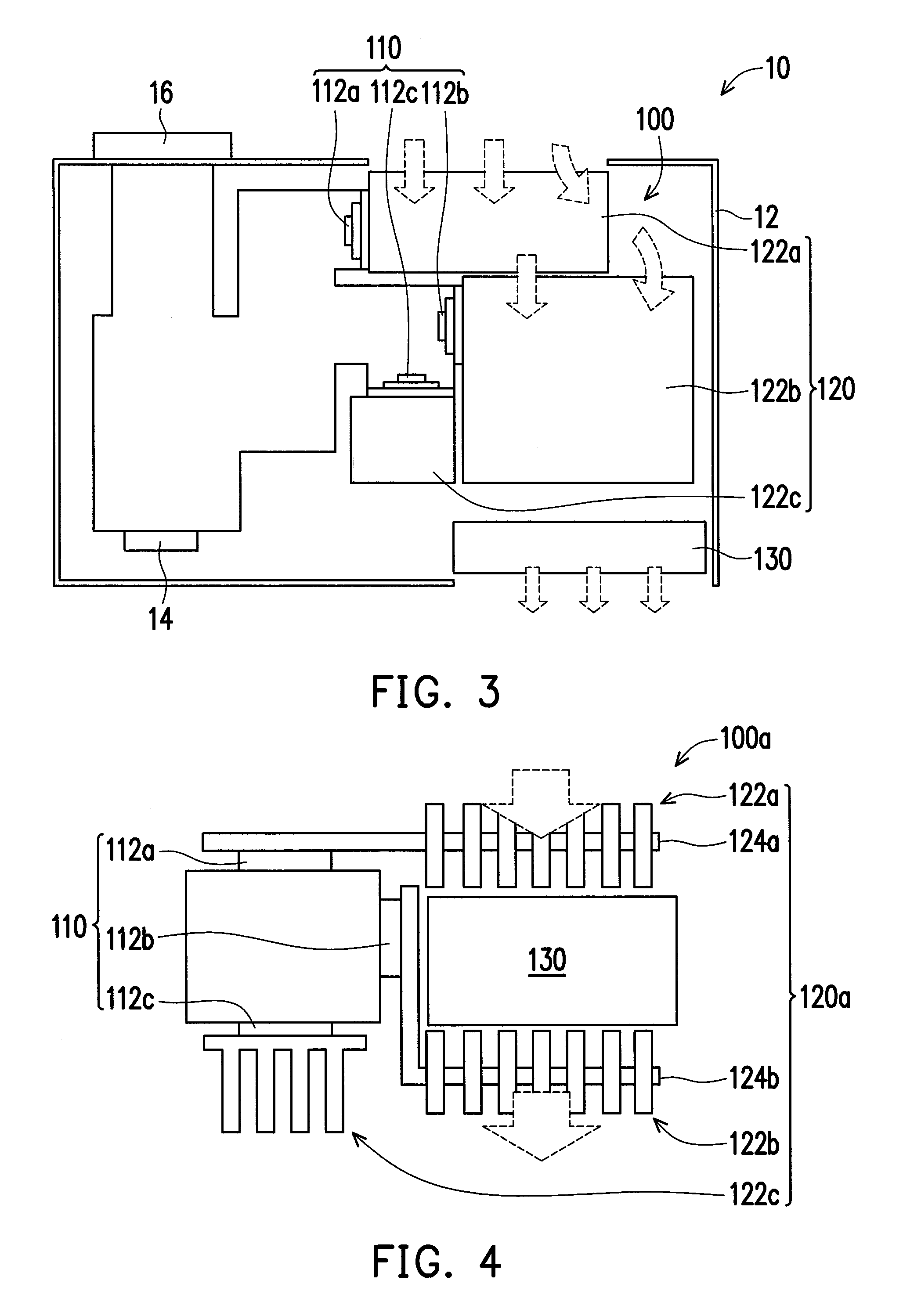
An illumination system adapted to be used in a projection apparatus is provided. The illumination system includes a solid-state light source group, a cooling module, and an ion fan. The cooling module is thermally coupled to the solid-state light source group. The cooling module is located on a path of a forced convection air generated by the ion fan. Moreover, the invention further discloses a projection apparatus including the aforementioned illumination system, and the projection apparatus avails prolonging a life time of the illumination system, and the ion fan does not have a magnetic shearing sound of a motor and a wind shearing sound of fan blades to avail reducing an operation noise of the illumination system.

Description

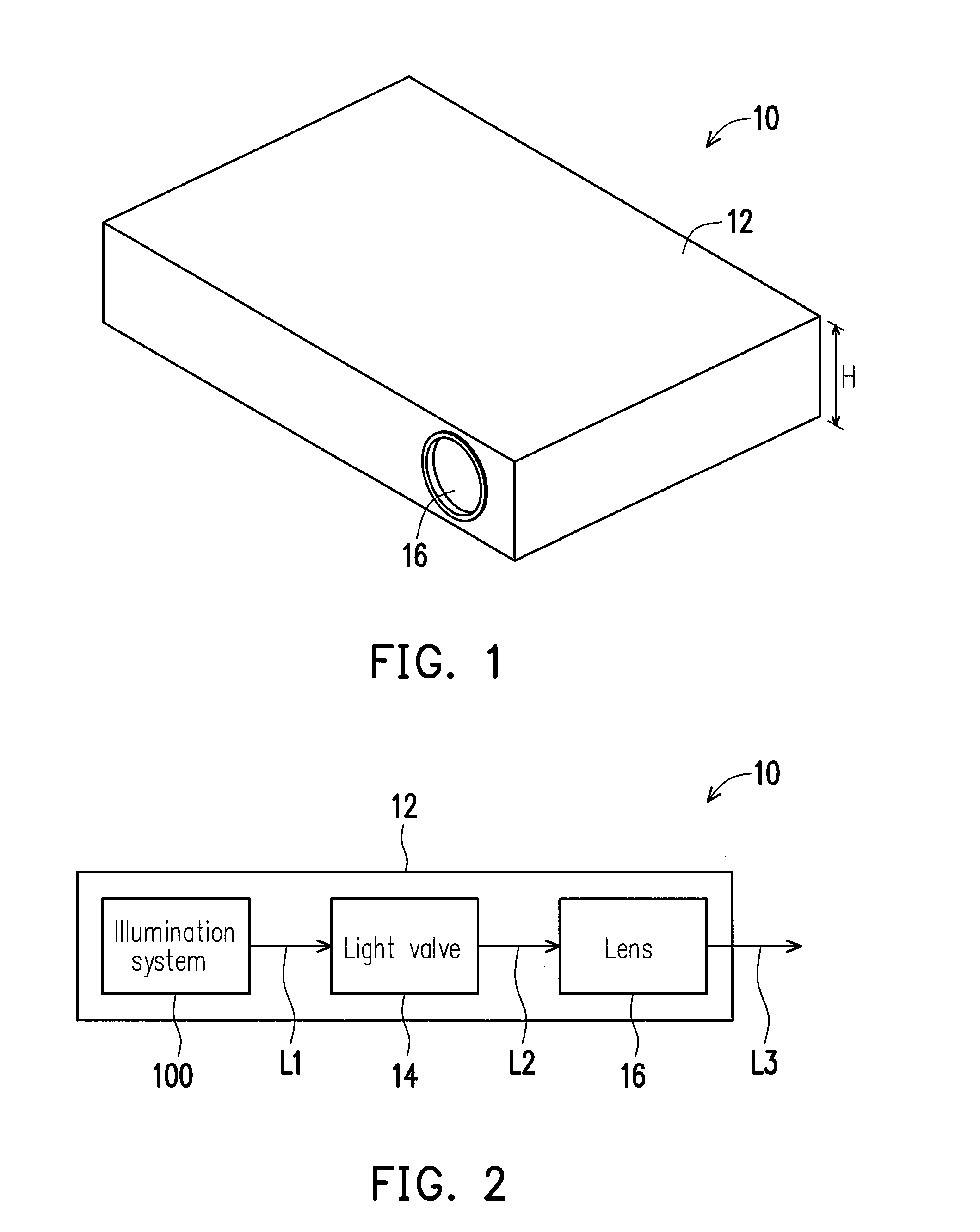
CROSS-REFERENCE TO RELATED APPLICATION[0001]This application claims the priority benefit of China application serial no. 201210369975.2, filed on Sep. 27, 2012. The entirety of the above-mentioned patent application is hereby incorporated by reference herein and made a part of this specification.BACKGROUND[0002]1. Technical Field[0003]The invention relates to an illumination system used in a projection apparatus and a projection apparatus using the illumination system.[0004]2. Related Art[0005]A projection apparatus is a display apparatus used for producing large size images. An imaging principle of the projection apparatus is to convert an illumination beam generated by a light source into an image beam through a light valve, and project the image beam onto a screen or a wall through a lens to form an image. Along with development of projection technology and reduction of fabrication cost, usage of the projection apparatus has gradually extended from commercial use to family use.[0...

Claims


Application Information

Patent Timeline
Patent Type & Authority Applications(United States)
IPC IPC(8): G03B21/16F21V29/00F21V29/02
CPCG03B21/16F21V29/26F21V29/02F21V29/60G03B21/20G03B21/2013G03B21/2033H04N9/31H04N9/3141H04N9/3144H04N9/3164H04N9/3173
Inventor WU, SHANG-HSUANGCHEN, JHIH-HAOLIN, TSUNG-CHINGCHUNG, WEN-YEN
Owner CORETRONIC
Why Eureka
Try Eureka