High Power Laser System with Multiport Circulator

Active Publication Date: 2014-03-27
IPG PHOTONICS CORP
View PDF0 Cites 31 Cited by
  • Summary
  • Abstract
  • Description
  • Claims
  • Application Information

AI Technical Summary

Benefits of technology

[0015]To effectively handle high powers, the disclosed router includes a case enclosing a plurality of optical components which are all mounted on a heat dissipating plate disposed upon one of the inner surfaces of the case. The heat dissipating plate is made from material with a high heat-conductive coefficient which effectively evacuates heat from the case. To provide the router with necessary ruggedness, the heat plate is covered by a layer of epo

Problems solved by technology

These devices have issues with handling high optical powers due to a number of reasons.
First, the optical beam size is very small due to the compact size of this device.
Second, the heat dissipation of the known devices may not be adequate because the heat path through epoxies and RTVs.
Third, stress birefringence, due to non-uniform heating of op

Method used


Image

  • High Power Laser System with Multiport Circulator
  • High Power Laser System with Multiport Circulator
  • High Power Laser System with Multiport Circulator

Examples


Example

[0031]Reference will now be made in detail to the disclosed high power laser system and circulator incorporated therein. Wherever possible, same or similar reference numerals are used in the drawings and the description to refer to the same or like parts or steps. The drawings are in simplified form, far from precise scale.

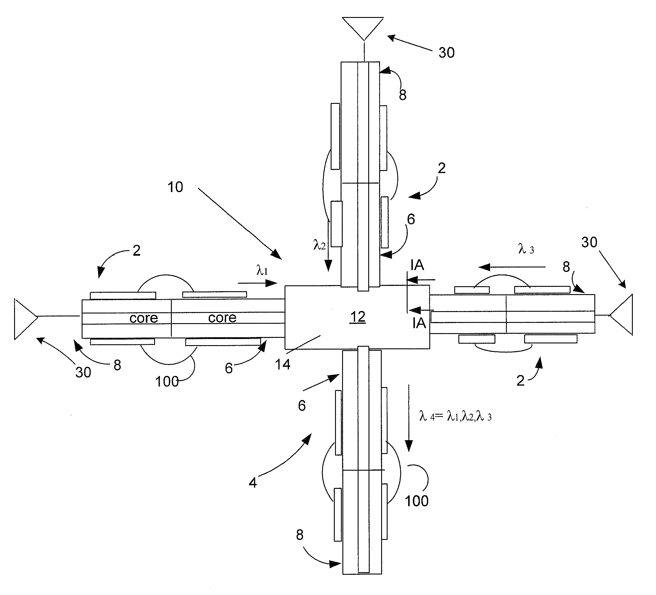
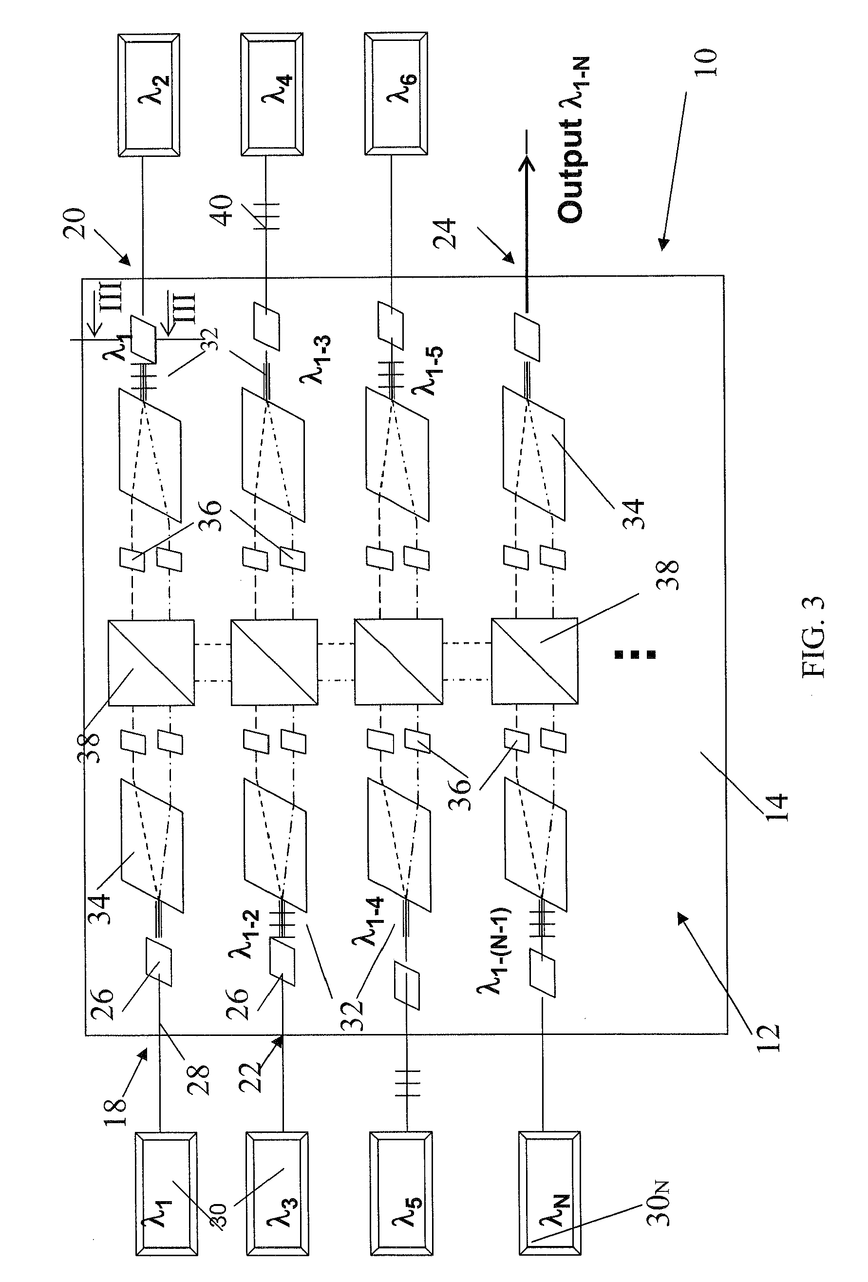
[0032]FIG. 1 illustrates a high power fiber laser system 10 including a directional fiber pigtailed router configured with a HP multi-port circulator 12 and a plurality of launching components 2 and receiving components 4. The launching component 2 is configured to deliver a SM signal into an input port 18 of circulator 12. The SM signal, after being guided along a predetermined path towards an output port 24, is coupled into receiving component 4 over free space. In case of additional ports 20 and 22, respectively, additional launching components 2 are configured to launch respective input signals into circulator 12 over tree space in such a way that multiple inp...


PUM


Abstract

A high power (HP) fiber circulator is configured with a case enclosing a plurality of optical components which are arranged so as to define multiple ports. The fiber circulator further includes a plurality of launching and receiving fiber components each of which has spliced delivery and pigtailed passive fibers selectively coupling a HP input signal into and receiving a HP output signal from respective input and output ports. The passive fibers of each fiber component have respective protective coatings spaced from one another and each covering the cladding of the fibers. A light stripper, extending between the protective coatings, is operative to substantially remove cladding-supported light from one of the passive fibers before it reaches the protective coating of the other passive fiber. At least one of the ports includes a wavelength selective component configured to direct the HP input light beam along the desired path between the ports and including a fiber Bragg grating, volume Bragg grating or a combination of these.

Description

BACKGROUND OF THE DISCLOSURE[0001]1. Field of the Disclosure[0002]The present disclosure relates generally to high power fiber laser systems, and in particular, to high power laser systems provided with a multi-port pigtailed directional selective router operating at high powers.[0003]2. Prior Art[0004]A multi-port optical component, such as circulators, is a light-directional device operative to route incoming signal between fibers. Configured as a multi-port structure, a circulator is operative to collect the light and direct it to a following output port. This operation is repeated over and over again depending on the number of ports. A light path between multiple ports is thus fixed and cannot be voluntarily changed.[0005]Typically, optical circulators are used for low power applications such as bi-directional wavelength division optical multiplexing, bi-directional wavelength division optical add / drop multiplexing, three-way channel separation, bi-directional optical amplificat...

Claims


Application Information

Patent Timeline
IPC IPC(8): G02B6/26
CPCG02B6/268G02B6/4296G02B6/02057G02B6/2746H01S3/0675H01S3/06758H01S3/06791H01S3/2391H01S3/005H01S3/0064H01S3/0092H01S2301/03
Inventor STARODUBOV, DMITRYYU, HONGBOYUSIM, ALEX
Owner IPG PHOTONICS CORP
Why Eureka
Try Eureka