Magnetic-enabled connector device

a magnetically enabled, connector technology, applied in the direction of coupling device connection, coupling contact member engagement/disengagement of coupling parts, coupling contact parts, etc., can solve problems such as improper orientation, and achieve the effect of reducing the risk of damage from misalignmen

Active Publication Date: 2014-03-27
KC MAGCON
View PDF6 Cites 106 Cited by
  • Summary
  • Abstract
  • Description
  • Claims
  • Application Information

AI Technical Summary

Benefits of technology

[0015]According to another aspect of the invention, contact pins are provided in a unique configuration which reduces the risk of damage from misalignment or otherwise. Contact pins on the male and female connector elements extend only a small amount beyond respective protective surfaces, such that the pins cannot be damaged from bending or breaking due to lateral forces. A male connector portion includes contact pins that ext...

Problems solved by technology

When the male and female connector portions are brought into proximity in the wrong orientation,...

Method used


Image

  • Magnetic-enabled connector device
  • Magnetic-enabled connector device
  • Magnetic-enabled connector device

Examples


Embodiment Construction

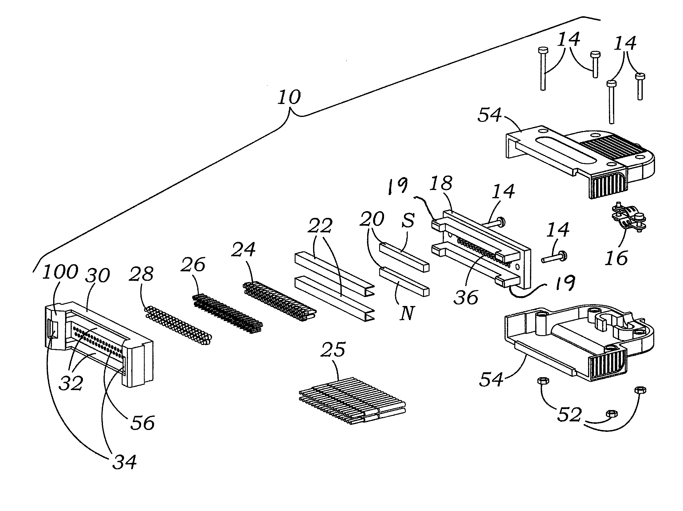
[0025]FIG. 1 is an exploded view of a female connector 10, according to an aspect of the invention. A plurality of conductive contact pins 28 are disposed within respective annular openings 56 formed in a main seat body 30 of female connector 10. Conductive contact pins 28 may be spring-biased by cooperating with springs 26 and pegs 24, which may be disposed in correspondingly-shaped recesses or cavities 36 formed in an adapter element 18, which cooperates with the main seat body 30 via, for example, threaded fasteners 14, to retain the pins 28, springs 26 and pegs 24 in an assembled position. Pegs 24 may include crimped connectors to receive and secure the ends of respective conductors or wires (not shown) from an electrical source and form a conductive path with springs 24 and pins 28. Referring additionally to FIG. 6, pins 28 may each include a narrow forward portion and a retaining collar or shoulder such that the forward portion is narrow enough to extend into the annular openi...


PUM


Abstract

An electrical connector, which may be a multi-pin connector, includes magnetic elements and mechanical alignment elements which provide connective forces and precision alignment and orientation. The magnetic elements permit a user to bring male and female connector portions only into “rough” alignment before magnetic forces bring the portions into the correct position. Pin contacts on the connector portions extend only a small amount beyond respective protective annular openings and are thereby protected. Spring-biased pin elements may be included on one of the connector portions to bias the contact pins into engagement and create conductive paths when the portions are in a connected position. Paramagnetic or non-magnetic sheaths may surround the magnetic elements to focus, or distribute, magnetic forces.

Description

CROSS-REFERENCE TO RELATED APPLICATIONS[0001]This application claims the priority benefit of U.S. Provisional Patent Application Ser. No. 61 / 744,432 titled “MAGNETIC-ENABLED CONNECTOR DEVICE,” filed on Sep. 26, 2012, the specification of which is incorporated in its entirety herein by reference.BACKGROUND[0002]1. Technical Field[0003]The disclosure relates to connectors for electronic devices and data communication. More particularly, the disclosure relates to self-aligning, magnetically biased connectors, including multi-pin connectors.[0004]2. Prior Art[0005]It is generally known to provide magnetic coupling elements in electrical and non-electrical connectors. Examples of connectors that include magnetic coupling elements are disclosed in U.S. Pat. Nos. 4,484,761; 4,776,406; 7,277,013 and 7,334,433. Examples of magnetic breakaway connection devices for power lines or cables are disclosed in U.S. Pat. Nos. 5,315,064 and 5,623,122.[0006]Examples of other types of electrical connect...

Claims


Application Information

Patent Timeline
IPC IPC(8): H01R13/62
CPCH01R13/6205H01R13/08
Inventor LEE, VINCENT
Owner KC MAGCON
Why Eureka
Try Eureka