
Method and system for determining qrs complexes in electrocardiogram signals

Active Publication Date: 2014-03-27
SAMSUNG ELECTRONICS CO LTD
View PDF1 Cites 16 Cited by
  • Summary
  • Abstract
  • Description
  • Claims
  • Application Information

AI Technical Summary

Benefits of technology

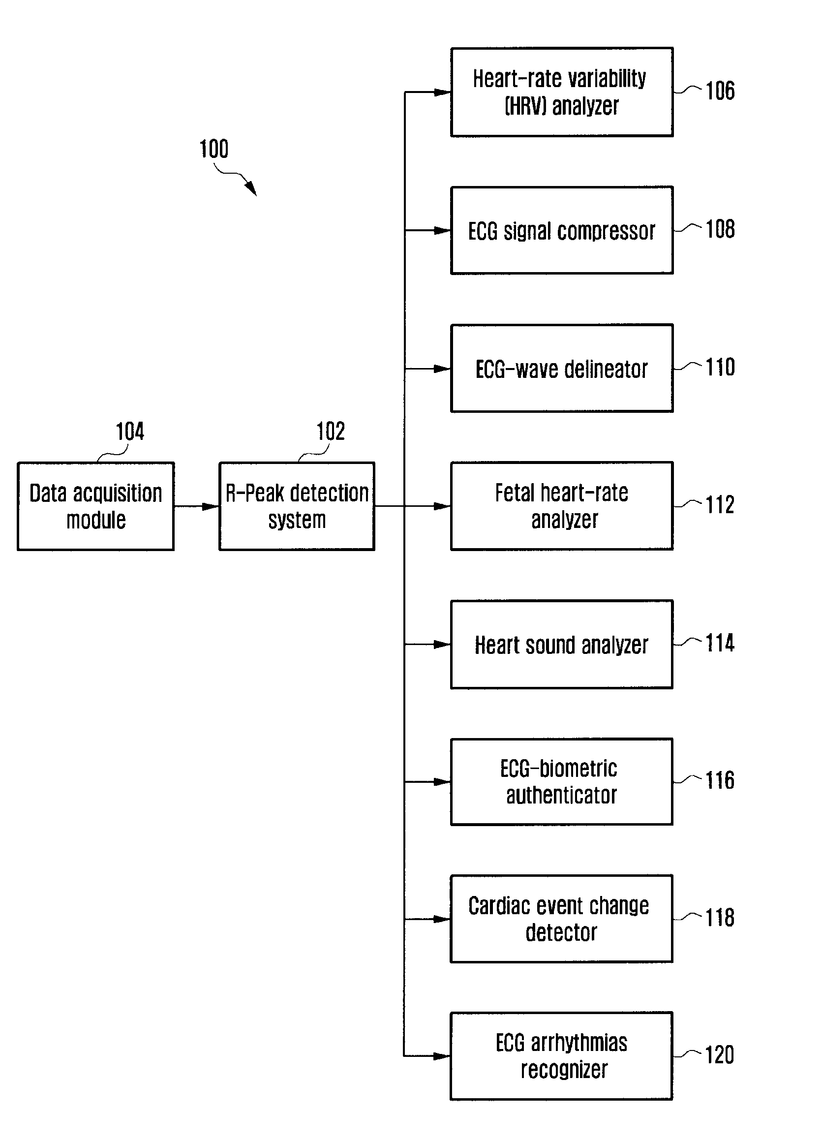
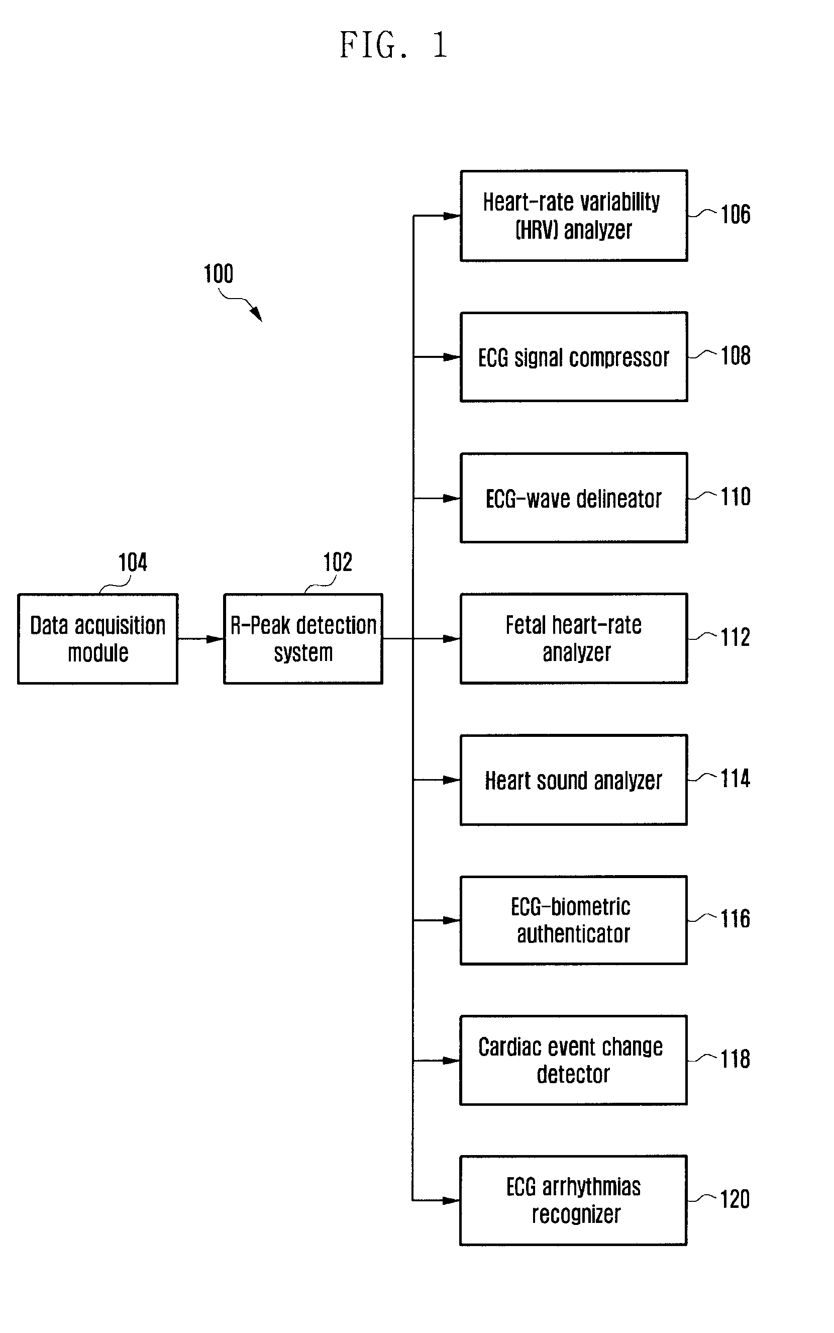
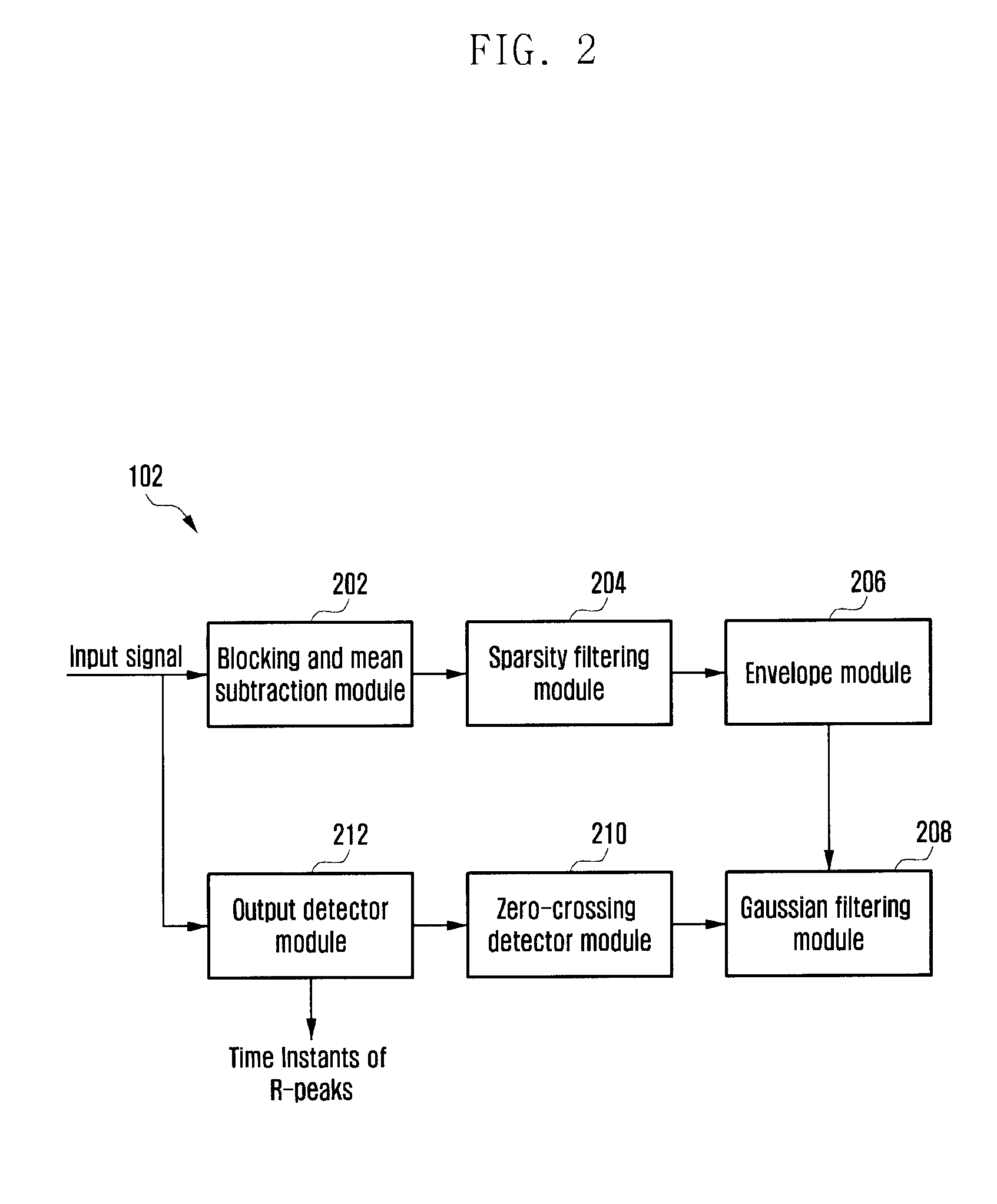
The invention is a system that can automatically detect and determine peaks in a received or recorded signal. It can smooth the signal to remove noise and enhance the peaks that are important. The system uses a zero-mean data sequence and an over-complete transform matrix to accurately detect peaks in the signal. It can also detect peaks in the filtered data sequence using a Gaussian filtering module. The system can be used in various digital signal processing applications to accurately detect peaks in signals.

Problems solved by technology

Although the known methods described above are effective in detecting R-peaks in an ECG signal, the known methods may have compromised performance when processing wide QRS complexes, low-amplitude QRS complexes, negative QRS polarities, sudden changes in RR intervals, sudden changes in QRS amplitudes, sudden changes in QRS morphologies, sharp P / T waves, and various kinds of noise (or artifacts) including baseline wander, power-line interference, muscle artifacts, electrosurgical noise, and motion artifacts.

Method used


Image

  • Method and system for determining qrs complexes in electrocardiogram signals
  • Method and system for determining qrs complexes in electrocardiogram signals
  • Method and system for determining qrs complexes in electrocardiogram signals

Examples


Embodiment Construction

[0029]The embodiments herein and the various features and advantageous details thereof are explained more fully with reference to the non-limiting embodiments that are illustrated in the accompanying drawings and detailed in the following description. For the purposes of clarity and simplicity, descriptions of well-known components and processing methods are omitted so as to not unnecessarily obscure the embodiments herein. The examples used herein are intended merely to facilitate an understanding of ways in which the embodiments herein can be practiced and to further enable those of skill in the art to practice the embodiments herein. Accordingly, the examples should not be construed as limiting the scope of the embodiments herein.

[0030]The system automatically determines time instants of R-peaks in a received or recorded signal using a sparsity filtering module to filter the signal and suppress baseline wander, power-line interference, muscle artifacts, motion artifacts, sharp P / ...


PUM


Abstract

A system automatically detects peaks in signal by generating a zero-mean data sequence of the signal comprising a data sequence and filtering the zero-mean data sequence. The entropy of the filtered data sequence is determined and peaks are detected in the entropy data sequence.

Description

CLAIM OF PRIORITY[0001]This application claims the benefit under 35 U.S.C. §119(a) from an Indian patent application filed on Sep. 27, 2012 in the Indian Patent Office and assigned Serial No. 3030 / DEL / 2012 and under 35 U.S.C. §119(a) of a Korean patent application filed on Aug. 9, 2013 in the Korean Intellectual Property Office and assigned Serial No. 10-2013-0094514, the entire disclosure of each of which is hereby incorporated by reference.BACKGROUND[0002]1. Field of the Invention[0003]The present invention concerns a signal processing system for peak detection in an electrocardiogram (ECG) signal processing and analysis system, for example.[0004]2. Description of the Related Art[0005]An electrocardiogram (ECG) waveform or signal includes a series of characteristic points conventionally designated by the letters P, Q, R, S, and T. The Q, R, and S portions of the wave when taken together are referred to as a “QRS complex”. The R-wave of the QRS complex is the most prominent wave in...

Claims


Application Information

Patent Timeline
IPC IPC(8): A61B5/04A61B5/0408A61B5/0456A61B5/00A61B5/352
CPCA61B5/04012A61B5/0456A61B5/0408A61B5/7203A61B5/316A61B5/352A61B5/25
Inventor MOTTAIYAN, SABARIMALAI MANIKANDANTYAGI, SAURABH
Owner SAMSUNG ELECTRONICS CO LTD
Learn More