Catheter having rib and spine structure supporting multiple electrodes for renal nerve ablation

a catheter and spine technology, applied in the field of percutaneous and intravascular devices for nerve modulation and/or ablation, can solve the problem of thermal injury to the vessel wall near the electrode, and achieve the effect of sufficient rf energy

Inactive Publication Date: 2014-03-27
BOSTON SCI SCIMED INC
View PDF21 Cites 35 Cited by
  • Summary
  • Abstract
  • Description
  • Claims
  • Application Information

AI Technical Summary

Benefits of technology

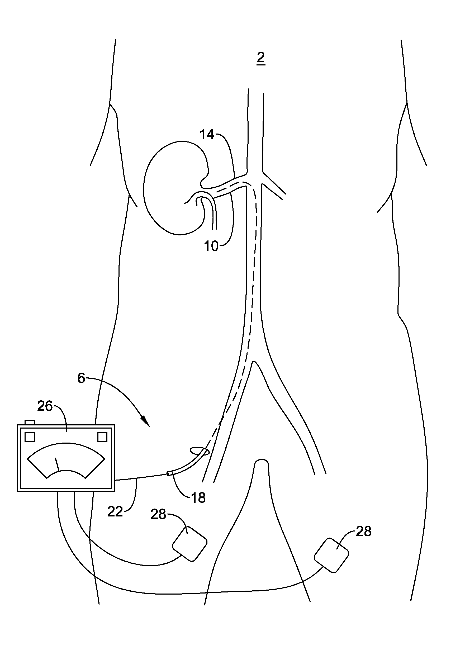
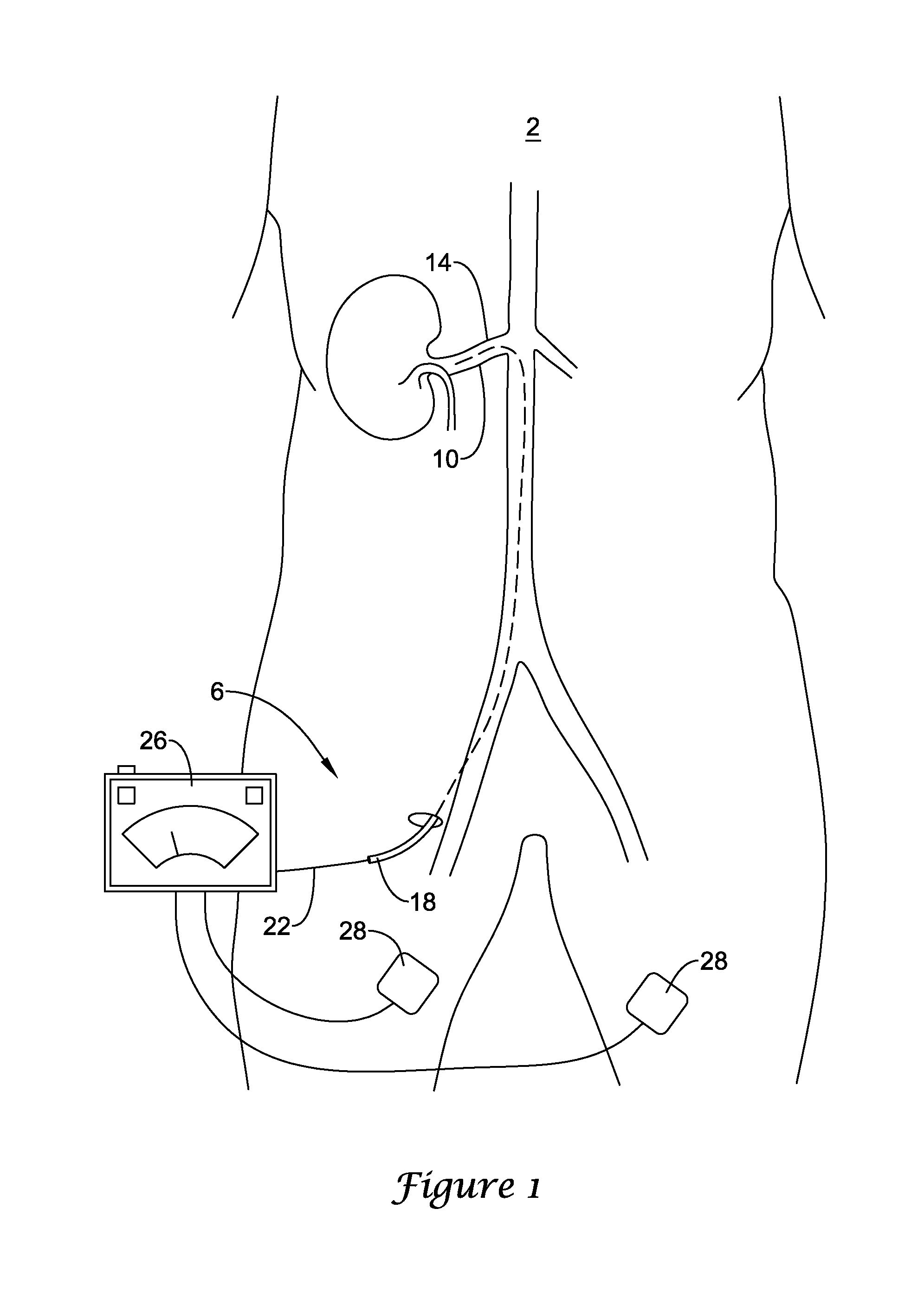
[0006]Some illustrative embodiments pertain to an intravascular catheter for modulating and / or ablating renal nerves which includes an elongated catheter body having an ablation region. The ablation region can include a flexible portion having a plurality of slots formed therein defining at least one spine extending along a length of the flexible portion and a plurality of ribs extending away from the spine such that the flexible portion is configured to transition from a first configuration suitable for delivery of the catheter to a second configuration having at least one bend, curve or turn suitable for ablating renal nerves. Additionally, the catheter can include at least one conductor extending within the elongated catheter body; two or more ablation elements coupled to the conductor extending within the elongated catheter body and located along the ablation region; and an actuation member coupled to the ablation region for transitioning the ablation region from the first configuration to the second configuration. In some embodiments, the two or more ablation elements are electrodes, wherein each electrode is configured to deliver sufficient RF energy so as to ablate renal nerves.

Problems solved by technology

However, such a treatment may result in thermal injury to the vessel wall near the electrode and other undesirable side effects such as, but not limited to, blood damage, clotting, weakened vessel wall, and / or protein fouling of the electrode.

Method used


Image

  • Catheter having rib and spine structure supporting multiple electrodes for renal nerve ablation
  • Catheter having rib and spine structure supporting multiple electrodes for renal nerve ablation
  • Catheter having rib and spine structure supporting multiple electrodes for renal nerve ablation

Examples


Embodiment Construction

[0017]For the following defined terms, these definitions shall be applied, unless a different definition is given in the claims or elsewhere in this specification.

[0018]All numeric values are herein assumed to be modified by the term “about”, whether or not explicitly indicated. The term “about” generally refers to a range of numbers that one of skill in the art would consider equivalent to the recited value (i.e., having the same function or result). In many instances, the term “about” may include numbers that are rounded to the nearest significant figure.

[0019]The recitation of numerical ranges by endpoints includes all numbers within that range (e.g., 1 to 5 includes 1, 1.5, 2, 2.75, 3, 3.80, 4, and 5).

[0020]As used in this specification and the appended claims, the singular forms “a”, “an”, and “the” include plural referents unless the content clearly dictates otherwise. As used in this specification and the appended claims, the term “or” is generally employed in its sense inclu...


PUM


Abstract

A catheter for ablating target tissue from a location within a body vessel includes an ablation region that is configured to transition from a first substantially straight configuration to a second configuration having a two-dimensional or three-dimensional shape. The ablation region may include a plurality of ablation elements that may be distributed along a length of the ablation region such that when the ablation region is in the second configuration, the ablation elements may be placed in closer proximity to the target tissue. Additionally, when the ablation region is in the second configuration, the ablation elements may achieve circumferential coverage of the body lumen or blood vessel, and as such, may be capable of ablating the target tissue at multiple locations along the length and around a circumference of the body lumen or vessel in a single step.

Description

CROSS-REFERENCE TO RELATED APPLICATIONS[0001]This Application claims the benefit under 35 USC §119 of U.S. Provisional Application No. 61 / 705,925, filed on Sep. 26, 2012, the entirety of which is incorporated herein by reference.TECHNICAL FIELD[0002]This disclosure generally relates to percutaneous and intravascular devices for nerve modulation and / or ablation.BACKGROUND[0003]Certain treatments may require the temporary or permanent interruption or modification of select nerve function. One example treatment is renal nerve ablation which is sometimes used to treat conditions related to hypertension and / or congestive heart failure. The kidneys produce a sympathetic response to congestive heart failure, which, among other effects, increases the undesired retention of water and / or sodium. Ablating some of the nerves running to the kidneys may reduce or eliminate this sympathetic function, which may provide a corresponding reduction in the associated undesired symptoms.[0004]Many bodily...

Claims


Application Information

Patent Timeline
Patent Type & Authority Applications(United States)
IPC IPC(8): A61B18/18
CPCA61B18/18A61B18/1492A61B2017/00309A61B2018/0016A61B2018/00214A61B2018/00434A61B2018/00511A61N1/0551
Inventor HILL, DAVID M.HILL, JASON P.
Owner BOSTON SCI SCIMED INC
Why Eureka
Try Eureka