Prosthesis for Transcatheter Valve Implantation

a transcatheter valve and prosthesis technology, applied in the field of prosthesis, can solve the problems of difficult to achieve, difficult to achieve, and difficult to achieve in a dual valve replacemen

Active Publication Date: 2014-03-27
MEDTRONIC VSACULAR GALWAY
View PDF2 Cites 91 Cited by
  • Summary
  • Abstract
  • Description
  • Claims
  • Application Information

AI Technical Summary

Benefits of technology

[0007]One or more embodiments hereof are directed to a dual valve prosthesis having first and second prosthetic valve sections. The first prosthetic valve section includes a stent structure with a first prosthetic valve secured therein and the second prosthetic valve section includes an annular frame with a second prosthetic valve secured therein, wherein the annular frame extends from the stent structure such that the first and second prosthetic valves are laterally offset from each other when the dual valve prosthesis is in an expanded configuration. In one embodiment, the annular frame forms a border that radially extends around the second prosthetic valve to define an apposition surface and has a profile of a flat washer. In a method in accordance herewith, the first and second prosthetic valve sections include prosthetic aortic and mitral valves, respectively, and...

Problems solved by technology

Whereas the use of minimally invasive techniques may be preferred, such an approach may be difficult in a dual valve replacement as placement of the prosthetic mitral valve prior to or subsequent of placement of the prosthetic aortic valve may be extremely difficult due to the relative locations of the two native valves, the lack of space in the left ventricle, and/or the concern of having to cross the first deployed prosthetic valve with the second delivery system and prosthetic valve under...

Method used


Image

  • Prosthesis for Transcatheter Valve Implantation
  • Prosthesis for Transcatheter Valve Implantation
  • Prosthesis for Transcatheter Valve Implantation

Examples


Embodiment Construction

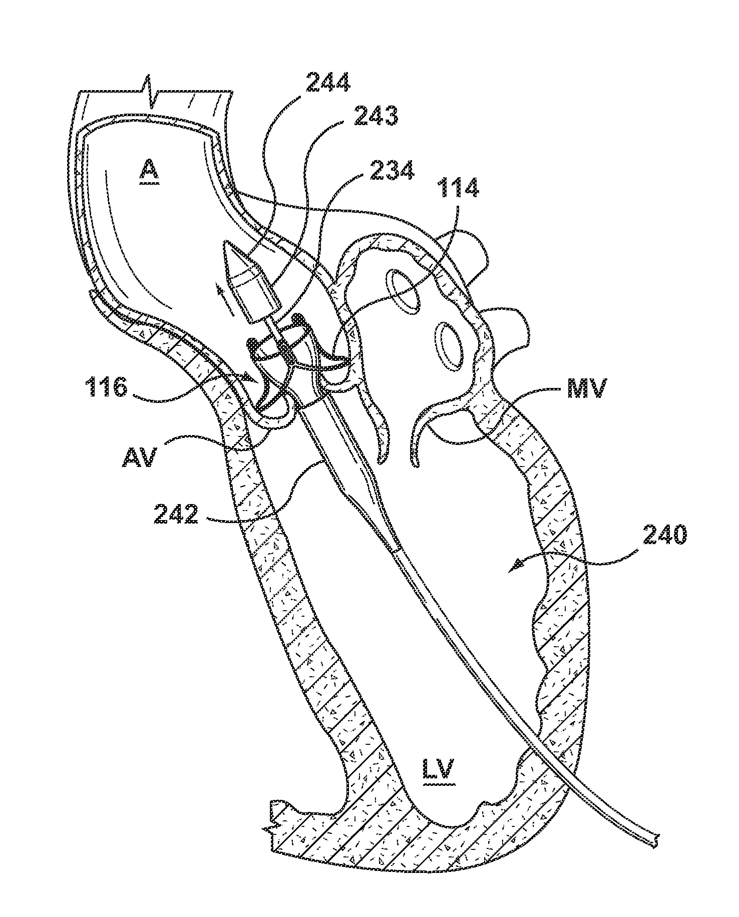
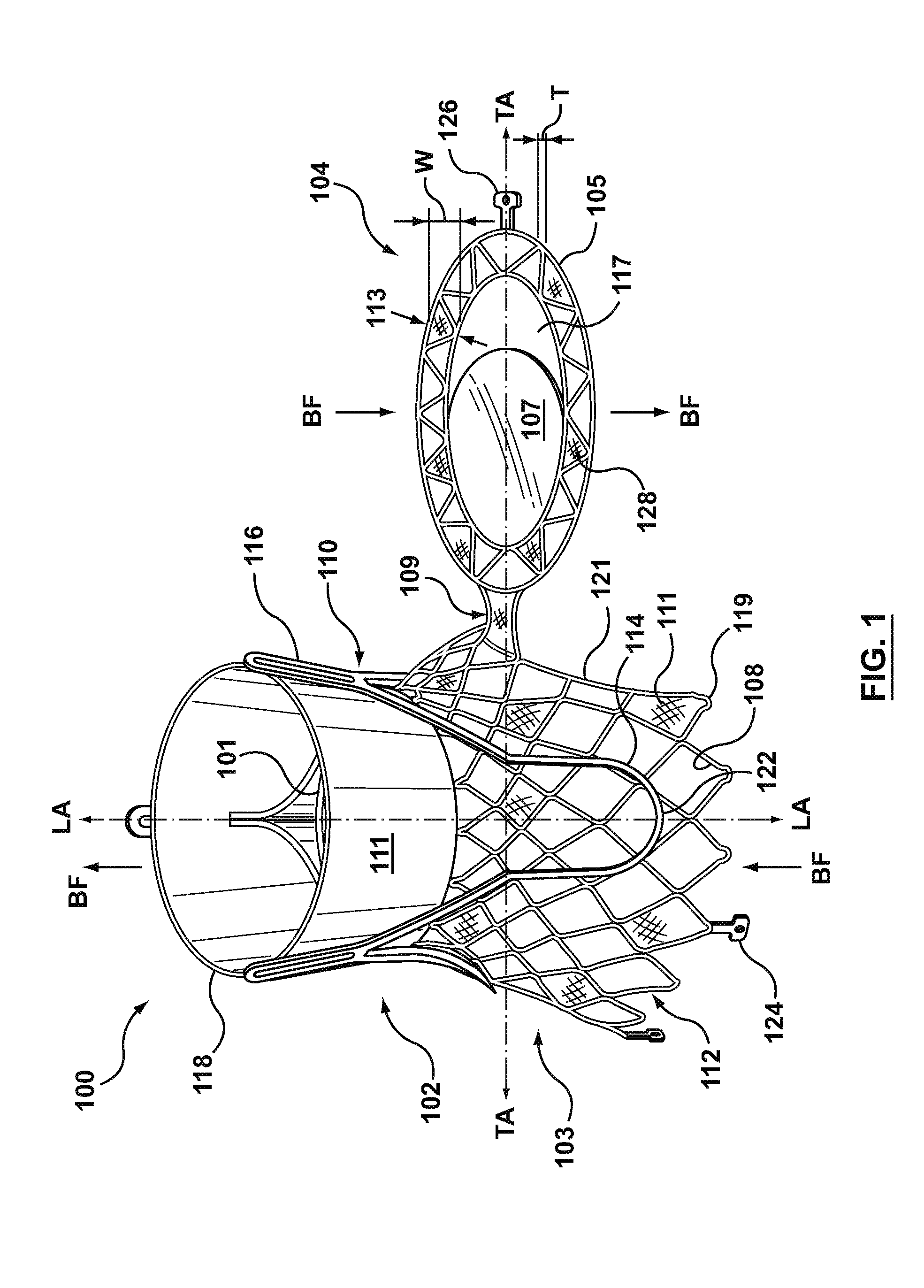
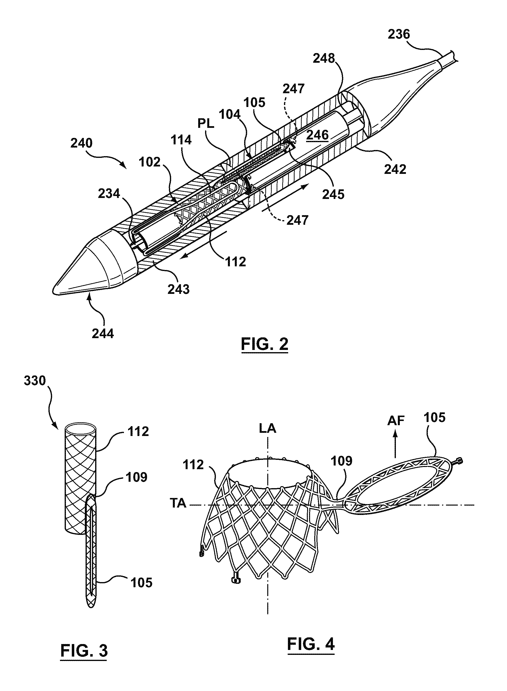
[0017]The following detailed description is merely exemplary in nature and is not intended to limit the invention or the application and uses of the invention. Although the description of embodiments hereof is in the context of concurrent aortic and mitral heart valve replacement, the invention may be adapted to be used for other concurrent valve replacement where it is deemed useful. Furthermore, there is no intention to be bound by any expressed or implied theory presented in the preceding technical field, background, brief summary or the following detailed description.

[0018]Specific embodiments of the present invention are now described with reference to the figures, wherein like reference numbers indicate identical or functionally similar elements. The terms “distal” and “proximal” are used in the following description with respect to a position or direction relative to the treating clinician. “Distal” or “distally” are a position distant from or in a direction away from the cli...


PUM


Abstract

A prosthesis having first and second prosthetic sections is disclosed. The first prosthetic section includes a stent structure that may contain a first prosthetic valve secured therein and the second prosthetic section includes an annular frame that may contain a second prosthetic valve secured therein. When the prosthesis is in an expanded configuration, the annular frame extends from the stent structure such that the first and second prosthetic sections are laterally offset from each other. In a method in accordance herewith, the first and second prosthetic sections may include prosthetic aortic and mitral valves, respectively, and the heart valve prosthesis is configured to replace one or both of the native aortic and mitral valves of the heart in a single transcatheter heart valve implantation procedure.

Description

RELATED APPLICATIONS[0001]This application is a Continuation in Part of and claims the benefit of U.S. patent application Ser. No. 13 / 432,497 filed Mar. 28, 2012. The disclosures of which are herein incorporated by reference in their entirety.FIELD OF THE INVENTION[0002]The invention relates generally to a prosthetic device for replacing a native valve or a previously implanted prosthetic valve in a non-surgical interventional procedure. In one embodiment, the invention relates to a dual valve prosthesis having a prosthetic aortic valve combined with a prosthetic mitral valve for concurrently replacing the corresponding native valves or previously implanted prosthetic valves in a non-surgical interventional procedure.BACKGROUND OF THE INVENTION[0003]A wide range of medical treatments are known that utilize “endoluminal prostheses.” As used herein, endoluminal prostheses are intended to mean medical devices that are adapted for temporary or permanent implantation within a body lumen,...

Claims


Application Information

Patent Timeline
IPC IPC(8): A61F2/24
CPCA61F2/2418A61F2/2436A61F2/2409A61F2220/0008A61F2220/0016A61F2220/005A61F2220/0058A61F2220/0075A61F2230/0054A61F2230/008
Inventor COSTELLO, DECLANGALLAGHER, JOHN
Owner MEDTRONIC VSACULAR GALWAY
Why Eureka
Try Eureka