
Contact patch simulation

Inactive Publication Date: 2014-03-27
APPLE INC
View PDF1 Cites 26 Cited by
  • Summary
  • Abstract
  • Description
  • Claims
  • Application Information

AI Technical Summary

Benefits of technology

This patent describes various methods, apparatus, and computer-readable media for determining the best way to machine a surface of a workpiece using a finishing tool. The method involves creating a model of the workpiece and tool, simulating the finishing process using finite element analysis, and then applying the determined amount of finishing force to the workpiece at specific points along the finishing path. This helps to achieve the desired surface finish and geometry. The surface finishing assembly includes a finishing tool, a robot, and a computer program for simulating the finishing operation and controlling the robot to apply finishing force to the workpiece. This technology helps improve the efficiency and accuracy of surface finishing processes.

Problems solved by technology

Imperfections in the surface finish can result in a component having an unacceptable appearance or, in some cases, compromised mechanical integrity.
Multiple separate tools to finish different regions of the component can require additional manufacturing time than when using fewer finishing tools that can produce a desired finish for both flat regions and three-dimensional curved regions.
The finishing tool can contact a variable surface area across different regions of the three-dimensional component and can result in a variable finish rather than uniform finish if the contact of the finishing tool is not adjusted continuously throughout the finishing process.

Method used


Image

  • Contact patch simulation
  • Contact patch simulation
  • Contact patch simulation

Examples


Embodiment Construction

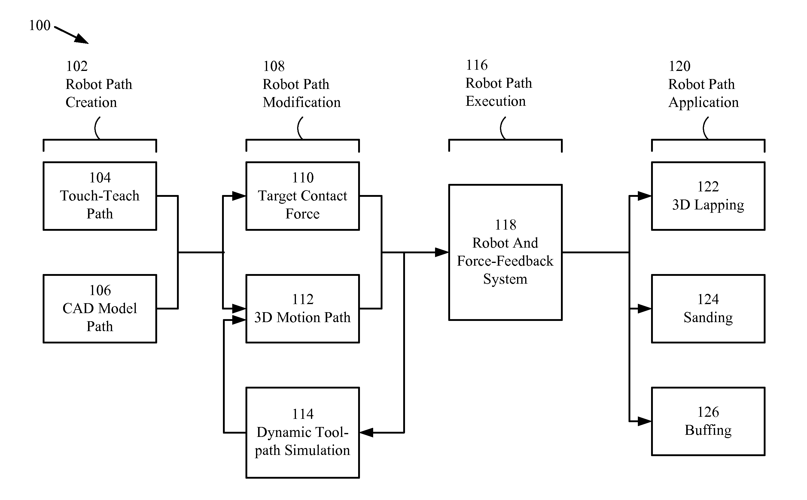
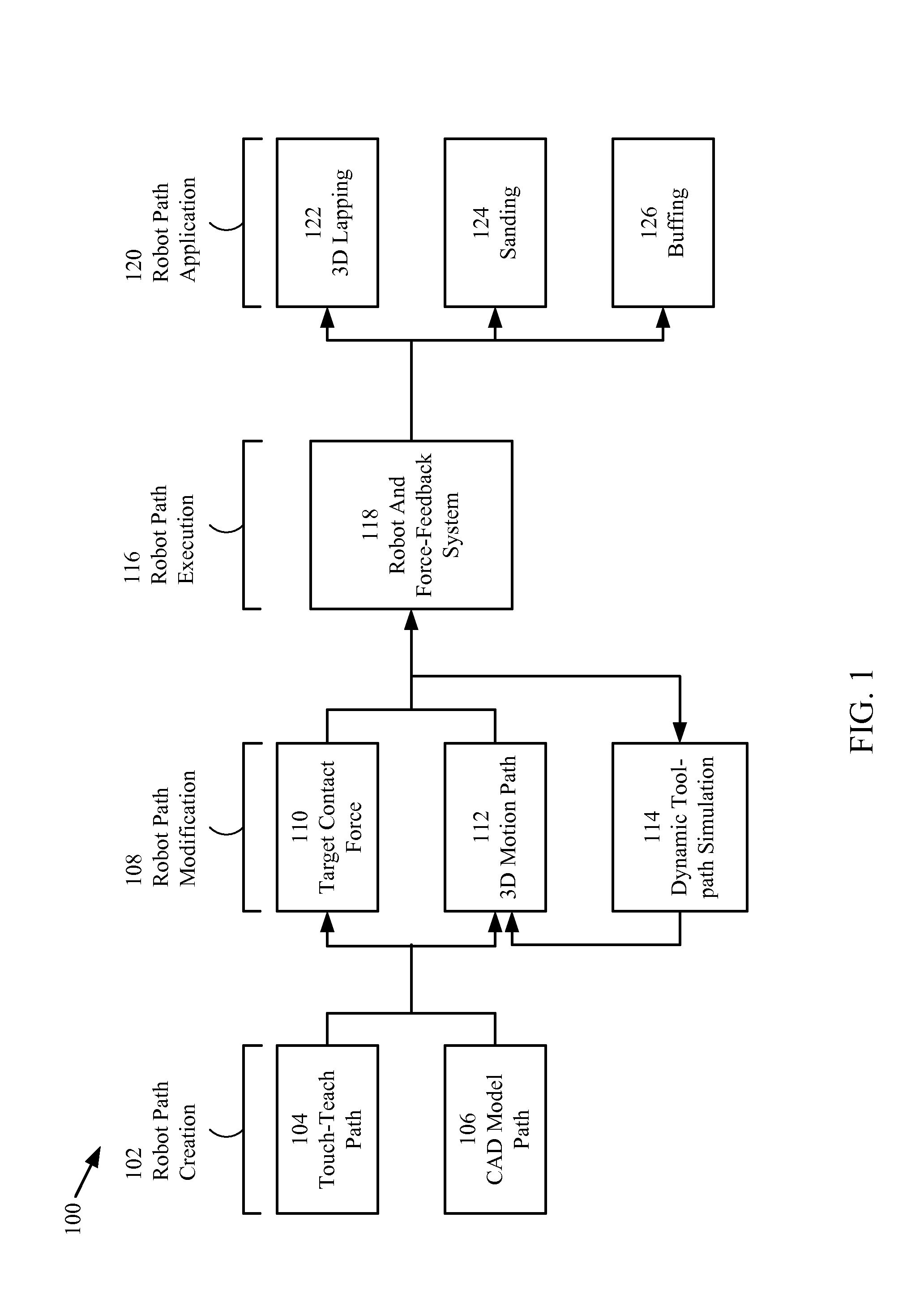
[0031]The present invention relates generally to robotic surface finishing of a three-dimensional object. More particularly, a method, system, and computer readable medium are described for developing a nominal path by finite element analysis simulation for use with robotic surface finishing of an exterior surface of a three-dimensional object to produce a desired surface finish on a three-dimensional complex shape.

[0032]In the following description, numerous specific details are set forth to provide a thorough understanding of the present invention. It will be apparent, however, to one skilled in the art that the present invention may be practiced without some or all of these specific details. In other instances, well known process steps have not been described in detail in order to avoid unnecessarily obscuring the present invention.

[0033]High volume manufactured electronic devices can include computer numerically controlled (CNC) machined parts with various geometrically shaped s...


PUM


Abstract

A method and an apparatus for smart automation of robotic surface finishing of a three-dimensional surface of a workpiece is described. A finite element analysis simulation is conducted providing data for generation of a three-dimensional path along the surface of the workpiece. The finite element can include properties of the workpiece, finishing tool, and the robot configured to maneuver the finishing tool. The surface of the workpiece is finished using one or more surface finishing tools along the three-dimensional path. The surface of the workpiece includes at least a flat region and a curved region.

Description

BACKGROUND[0001]1. Technical Field[0002]The present invention relates generally to robotic surface finishing of a three dimensional object. More particularly, applying finite element analysis for reducing design development times of smart automation routines associated with robotic surface finishing.[0003]2. Related Art[0004]The proliferation of high volume manufactured, electronic devices has encouraged innovation in both functional and aesthetic design practices for enclosures that encase such devices. Manufactured devices can include components that provide an ergonomic shape and aesthetically pleasing visual appearance desirable to the user of the device. A representative component can include a casing for the manufactured device; however, the embodiments described herein can apply equally to other three-dimensional objects having a complex surface and requiring an exacting and uniform surface finish. Other representative components can include an automotive body panel, a turbin...

Claims


Application Information

Patent Timeline
IPC IPC(8): G05B19/18
CPCB25J9/1684G05B19/4099G05B2219/35009G05B2219/35167G05B2219/35168G05B2219/45062G05B2219/50207Y02P90/02
Inventor MALONEY, MAX A.BUJTOR, HOWARD E.MIEHM, BRIAN K.
Owner APPLE INC
Learn More