Stylus device for touch screen

a touch screen and stylus technology, applied in the field of stylus or pen, can solve the problems of distortion of the electrostatic field of the screen, insufficient accuracy of the existing device for technical drawing, and inability to provide good feel or feedback for writing or drawing, etc., to achieve the effect of avoiding sharp edges which may damage the screen, facilitating capacitive activity, and ensuring the effect of accuracy

Inactive Publication Date: 2013-06-06
DUNAGAN KELLY ALLAN
View PDF2 Cites 16 Cited by
  • Summary
  • Abstract
  • Description
  • Claims
  • Application Information

AI Technical Summary

Benefits of technology

[0010]The tip may have an undercut immediately behind the working surface or interface. This provides an expanded field of vision for the user, allowing for a better view of the immediate activity at the screen through removal of obstructing material from the rear side of the interface surface. The interface surface may also have a blend radius at its outer periphery between the interface surface and undercut region, avoiding any sharp edges which may damage the screen. The interface surface has a circular periphery in one embodiment. The dimensions of the interface surface are selected to provide sufficient surface area for capacitive activity.

Problems solved by technology

A stylus is generally required for writing or drawing on such panels, but existing devices are not sufficiently accurate for technical drawing, and also do not provide good feel or feedback for writing or drawing.
Touching the surface of the screen with a finger or with a conductive stylus results in a distortion of the screen's electrostatic field, and the resultant change in capacitance is detected as an input by the controller.
In some cases, the user's view of the screen is limited by the handle.
Holding of the stylus stem or barrel can also be awkward where the tip is aligned with the handle axis, since the handle cannot be kept at the natural angle of attack of traditional writing instruments to the writing surface while keeping the tip at the proper angle of engagement to the screen.

Method used


Image

  • Stylus device for touch screen
  • Stylus device for touch screen
  • Stylus device for touch screen

Examples


Embodiment Construction

[0023]Certain embodiments as disclosed herein provide for a stylus device having a tip for writing or drawing on touch screens such as capacitive touch screen of cell phones, personal digital assistants, video games, computers, and the like.

[0024]After reading this description it will become apparent to one skilled in the art how to implement the invention in various alternative embodiments and alternative applications. However, although various embodiments of the present invention will be described herein, it is understood that these embodiments are presented by way of example only, and not limitation. As such, this detailed description of various alternative embodiments should not be construed to limit the scope or breadth of the present invention.

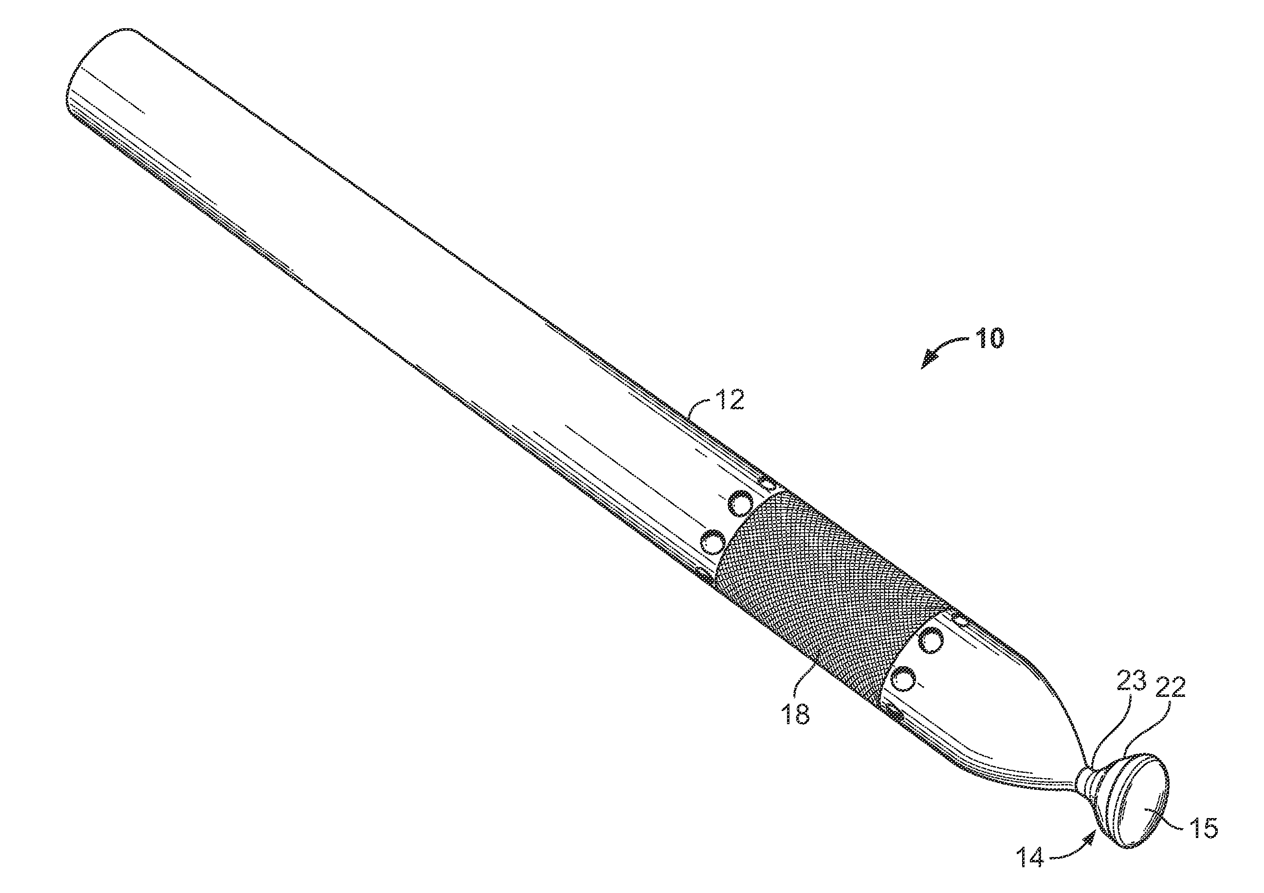
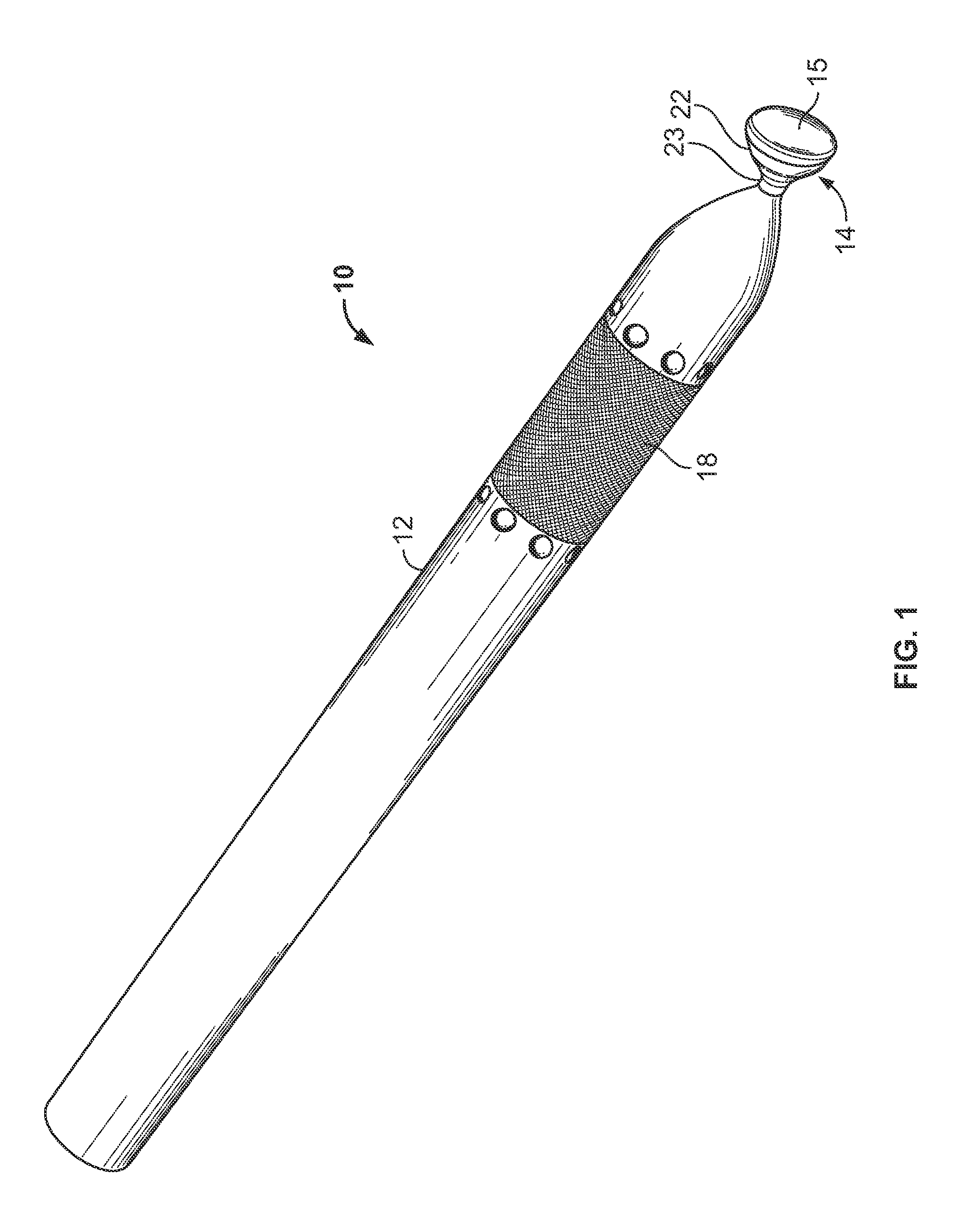
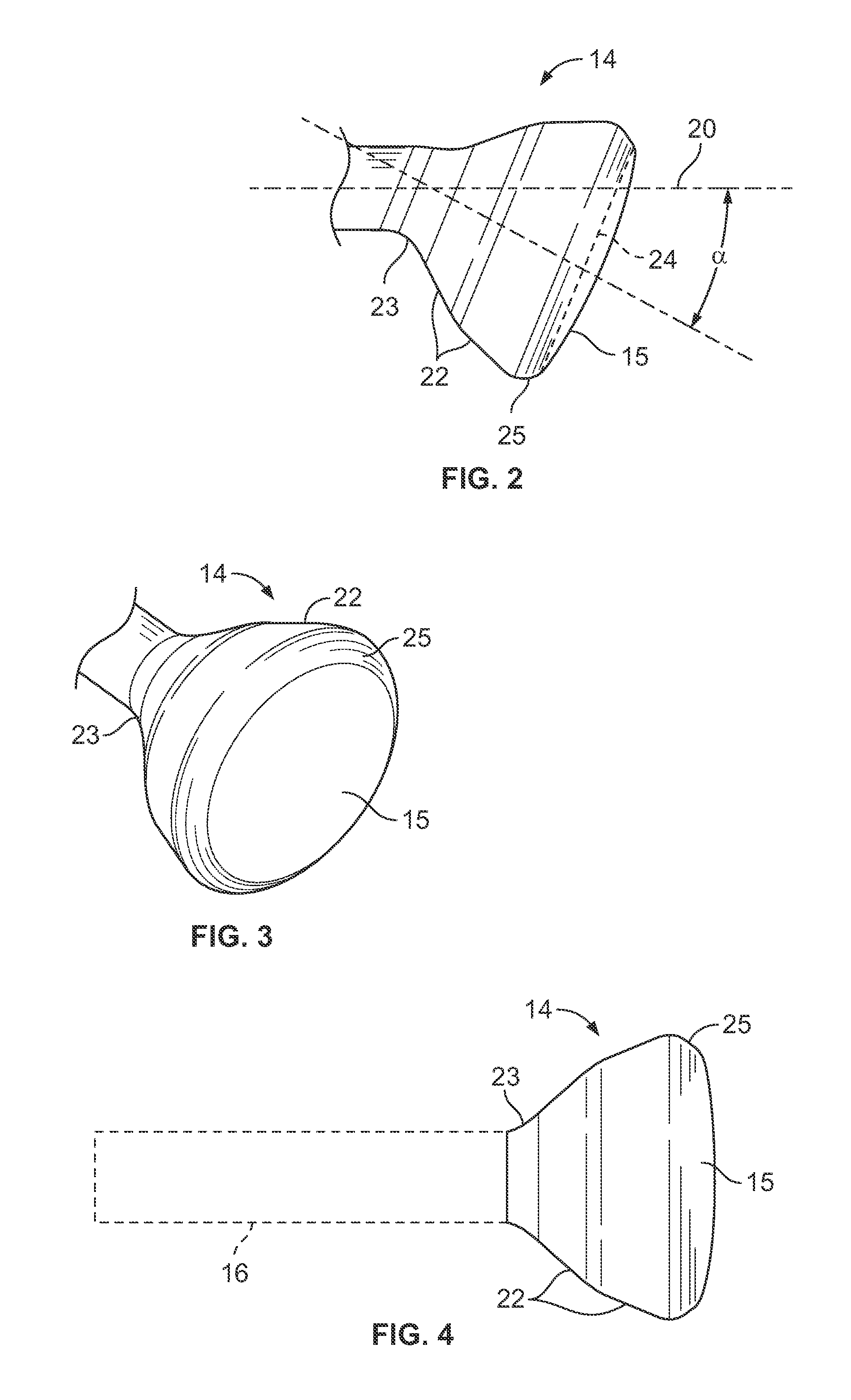
[0025]FIGS. 1 to 10 illustrate one embodiment of a stylus tip device 10 which has a pen or pencil-like elongate body or barrel 12 for gripping by a user and a head or stylus tip 14 having an interface or working surface or end face 15 co...


PUM


Abstract

A stylus device for writing or drawing on a touch screen has an elongate barrel for gripping by a user and a stylus tip of rigid, non-compressible material secured to one end of the barrel and having an end face comprising a working surface configured for contact with the touch screen while writing or drawing. The stylus tip is oriented at a predetermined offset angle to the longitudinal axis of the barrel, such that the working surface is not perpendicular to the central longitudinal axis of the barrel. The working surface is applied to a touch screen to develop a contact patch between the working surface and screen sufficient to trigger an input on the screen.

Description

BACKGROUND[0001]1. Field of the Invention[0002]The present invention generally relates to a stylus or pen-like device used to input commands, hand written text or drawings on a touch screen of devices such as cell phones, personal digital assistants, video games, computers, and the like, and is particularly concerned with a tip for a touch screen stylus.[0003]2. Related Art[0004]Touch screen panels detect touching of the screen surface by a user's finger or a stylus to enable entry of commands. A stylus is generally required for writing or drawing on such panels, but existing devices are not sufficiently accurate for technical drawing, and also do not provide good feel or feedback for writing or drawing. There are several types of touch screen device, including resistive and capacitive touch screens. Resistive touch screens have two metal layers separated by a narrow gap. Touching the screen with a finger or writing instrument causes the layers to come into contact at the point wher...

Claims


Application Information

Patent Timeline
Patent Type & Authority Applications(United States)
IPC IPC(8): G06F3/033
CPCG06F3/03545
Inventor DUNAGAN, KELLY ALLAN
Owner DUNAGAN KELLY ALLAN
Why Eureka
Try Eureka