System for optimizing the charging of electric vehicles using networked distributed energy storage systems

a technology of energy storage system and electric vehicle, which is applied in the direction of process and machine control, greenhouse gas reduction, instruments, etc., can solve the problems of high energy cost for users, high energy high cost of energy storage medium, especially battery energy storag

Active Publication Date: 2014-03-27
STEM
View PDF1 Cites 62 Cited by
  • Summary
  • Abstract
  • Description
  • Claims
  • Application Information

AI Technical Summary

Benefits of technology

[0018]Embodiments of the invention may further provide a method of controlling energy transferred between an electric grid and an electric load location comprises monitoring a first rate of energy transfer from an electric power line to the electric load location, wherein the electric power line is coupled to an electric meter adapted to determine power transferred between the electric load

Problems solved by technology

The cost to a utility for generating or purchasing electrical energy increases dramatically during periods of peak use versus periods of off-peak usage.
The higher rates charged during peak usage periods can lead to significantly higher energy costs for the user, especially when the user's period(s) of high demand coincides with or falls within the interval set by the utility as peak hours.
Energy storage mediums, especially battery energy storage, are expensive and, while various techniques are known by which an energy storage system can be used to optimize energy use at a business or home, such techniques are generally inefficient in applying stored energy to effectively control the energy use at an electric load location.
Consequently, an impractical quantity of energy storage mediums are required at an electric load location to realize useful energy arbitrage.
Each of these approaches generally requires an uneconomical amount of energy storage capacity in order to offset demand peaks at the electric load location.
Furthermore, use of a single demand set-point typically results in an energy storage system running out of energy storage availability due to over-reaction of the controlling components to the demand set point set by

Method used


Image

  • System for optimizing the charging of electric vehicles using networked distributed energy storage systems
  • System for optimizing the charging of electric vehicles using networked distributed energy storage systems
  • System for optimizing the charging of electric vehicles using networked distributed energy storage systems

Examples


Embodiment Construction

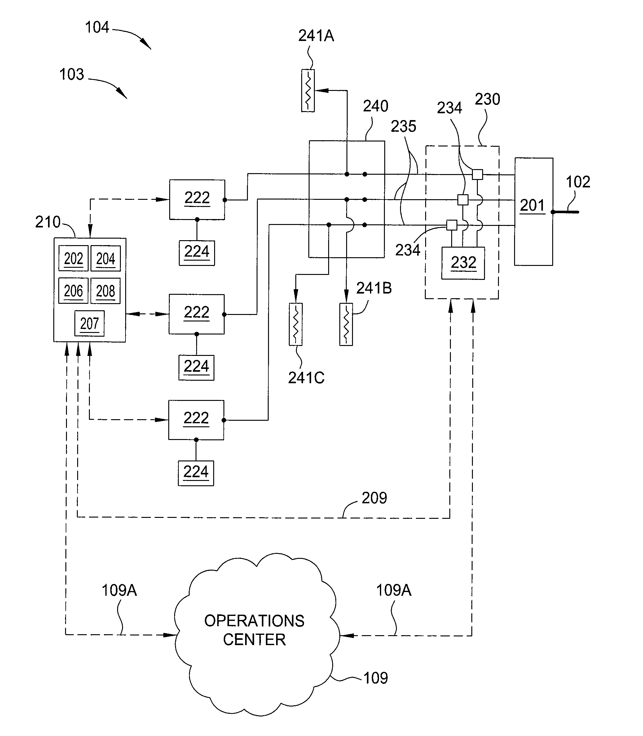
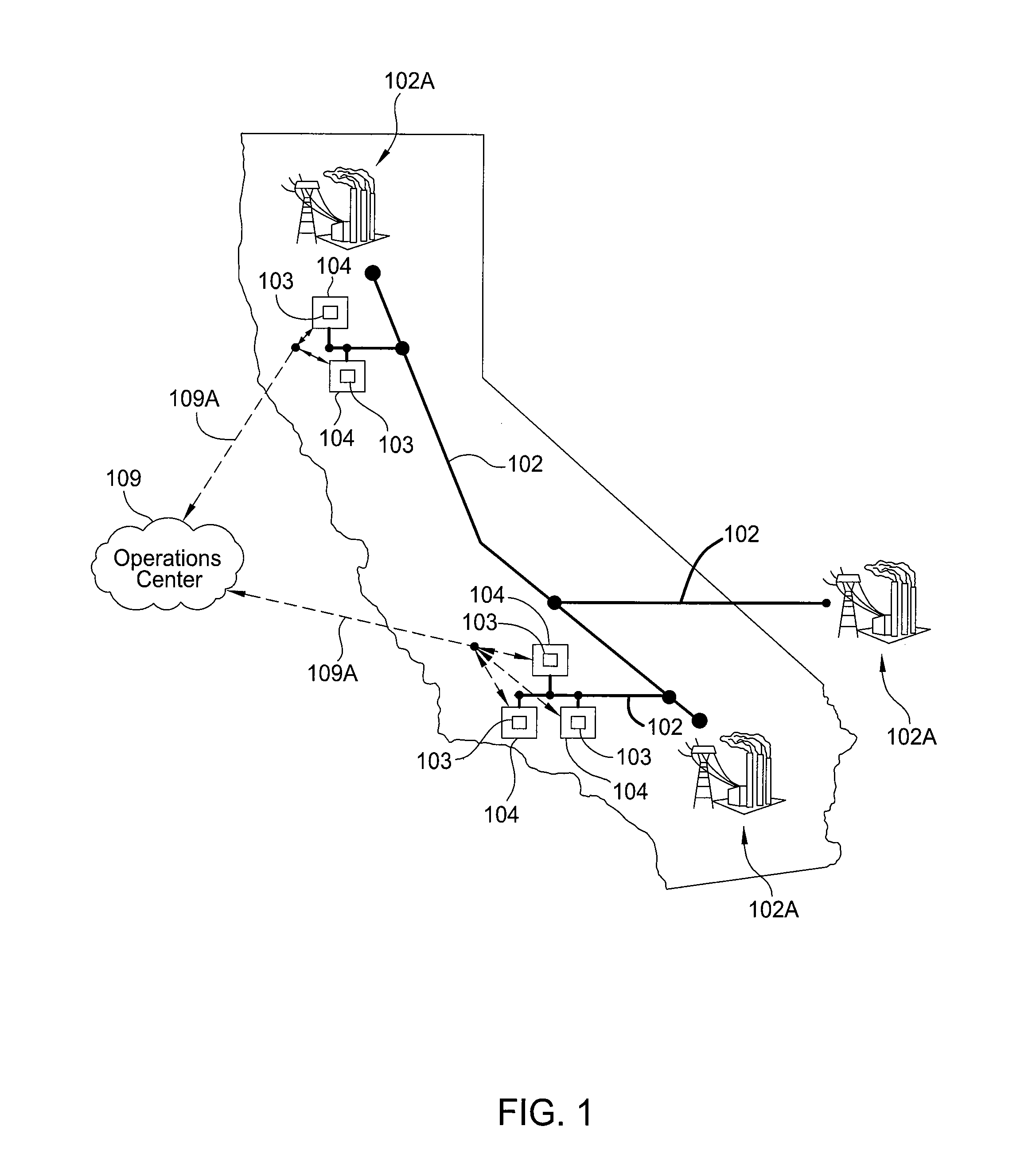
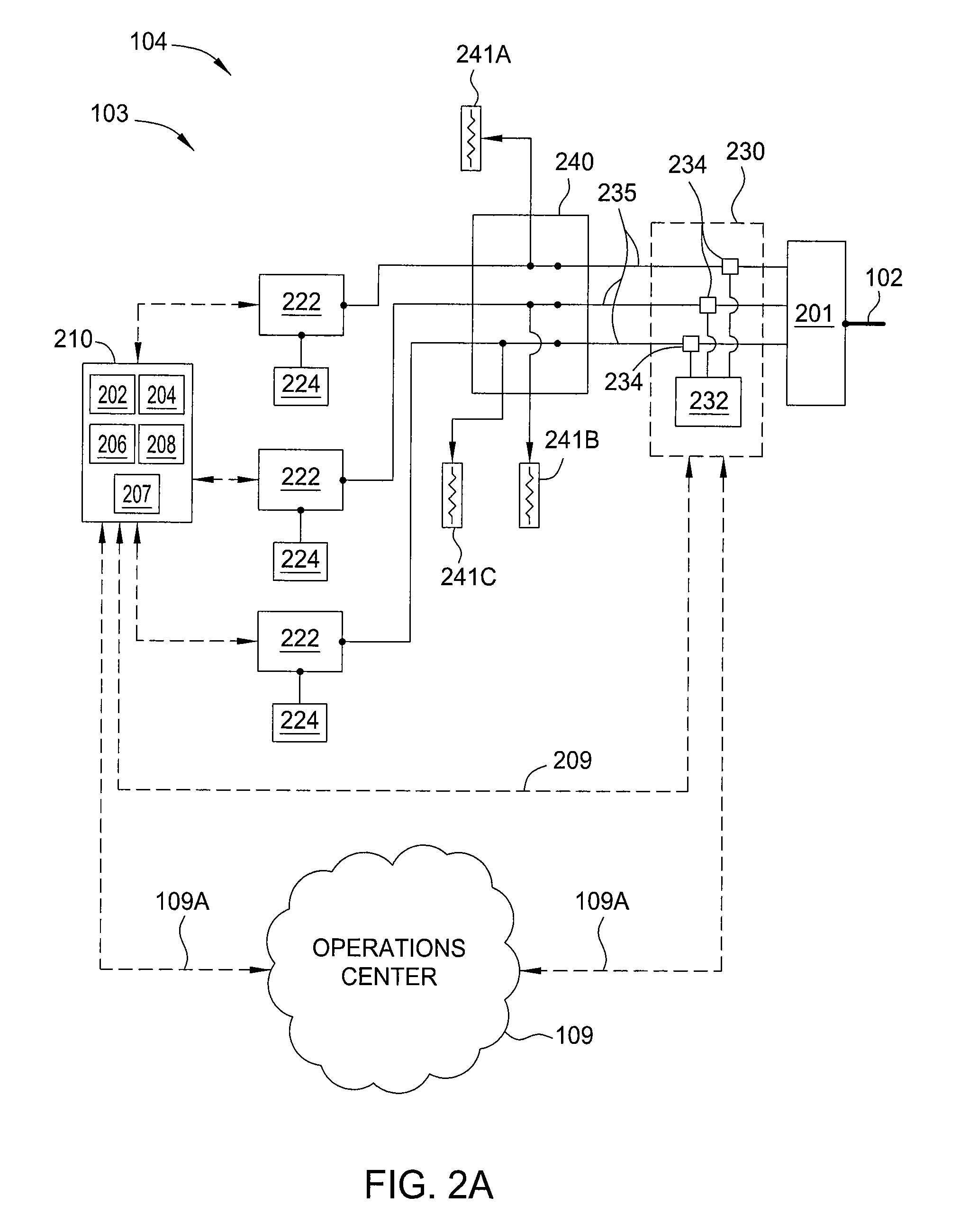
[0045]Embodiments of the present invention include control methods employed in multiphase distributed energy storage systems that are located behind utility meters typically located at, but not limited to, medium and large commercial and industrial locations. Some embodiments of the invention use networked multiphase distributed energy storage systems located at an electric load location 104 or installed at interconnection points along the electric power distribution grid 102 to provide a means for balancing the load created from an electric charging station, which are adapted to transfer power between one or more electric vehicles and the electric power grid 102.

[0046]According to such control methods, these multiphase distributed energy storage systems operate semi-autonomously at the electric load location, but each may be in frequent contact with a cloud-based optimization engine that is configured to develop energy control solutions based on various data inputs and to communica...


PUM


Abstract

Embodiments of the present invention include control methods employed in multiphase distributed energy storage systems that are located behind utility meters typically located at, but not limited to, medium and large commercial and industrial locations. Some embodiments of the invention use networked multiphase distributed energy storage systems located at an electric load location or installed at interconnection points along the electric power distribution grid to provide a means for balancing the load created from an electric charging station, which are adapted to transfer power between one or more electric vehicles and the electric power grid.

Description

CROSS-REFERENCE TO RELATED APPLICATIONS[0001]This application claims the benefit of U.S. Provisional Patent Application Ser. No. 61 / 706,091, filed Sep. 26, 2012 [Atty. Dkt No. STEM / 0013L] and U.S. Provisional Patent Application Ser. No. 61 / 801,274, filed Mar. 15, 2013 [Atty. Dkt No. STEM / 0016L], which are all hereby incorporated herein by reference.BACKGROUND OF THE INVENTION[0002]1. Field of the Invention[0003]Embodiments of the present invention generally relate to a method and an apparatus for controlling fluctuations in power and amount of power used at an electric load location and / or on an electrical grid.[0004]2. Description of the Related Art[0005]Energy demand at a commercial site, such as a business, or at home will vary over the time of day. In a typical home or hotel setting, there is a peak in the morning when the occupants get up and when the occupants return home at the end of the day. This typically creates two demand peaks during a normal day. Commercial buildings t...

Claims


Application Information

Patent Timeline
IPC IPC(8): H02J3/14
CPCH02J3/14Y04S10/126Y04S20/12H02J7/00712H02J2300/20H02J3/381H02J13/00034Y02B90/20Y02E60/00Y02P80/10Y04S20/222Y02B70/3225H02J13/00022H02J3/322H02J13/00002H02J2300/22Y04S40/126Y04S10/123Y02E70/30H02J3/00H02J3/38Y02E40/70
Inventor KEARNS, BENHYDE, III, HENRY HOLBROOKBURLINSON, JONSTEVENS, DREW
Owner STEM
Why Eureka
Try Eureka