Dynamic redundancy mapping of cache data in flash-based caching systems

Active Publication Date: 2014-03-27
AVAGO TECH INT SALES PTE LTD
View PDF18 Cites 22 Cited by
  • Summary
  • Abstract
  • Description
  • Claims
  • Application Information

AI Technical Summary

Benefits of technology

[0006]Accordingly, a method is included for managing redundancy of data in a solid-state cache system, wherein the solid-state cache system includes at least three solid-state storage modules. The method may include designating one or more extents of each dirty mirror pair to be of a particular priority order of at least two priority orders. The at least two priority orders includes at least a highest priority order, whereby the highest priority order has a higher relative priority than any other priority order of the at least two p

Problems solved by technology

However, the use of RAID 1 mirroring in a two-module flash-based cache system effectively reduces data capacity of the two-module cache-system to an equivalent of one module.
Currently,

Method used


Image

  • Dynamic redundancy mapping of cache data in flash-based caching systems
  • Dynamic redundancy mapping of cache data in flash-based caching systems
  • Dynamic redundancy mapping of cache data in flash-based caching systems

Examples


Embodiment Construction

[0016]Reference will now be made in detail to the subject matter disclosed, which is illustrated in the accompanying drawings. The scope of the invention is limited only by the claims; numerous alternatives, modifications, and equivalents are encompassed. For the purpose of clarity, technical material that is known in the technical fields related to the embodiments has not been described in detail to avoid unnecessarily obscuring the description.

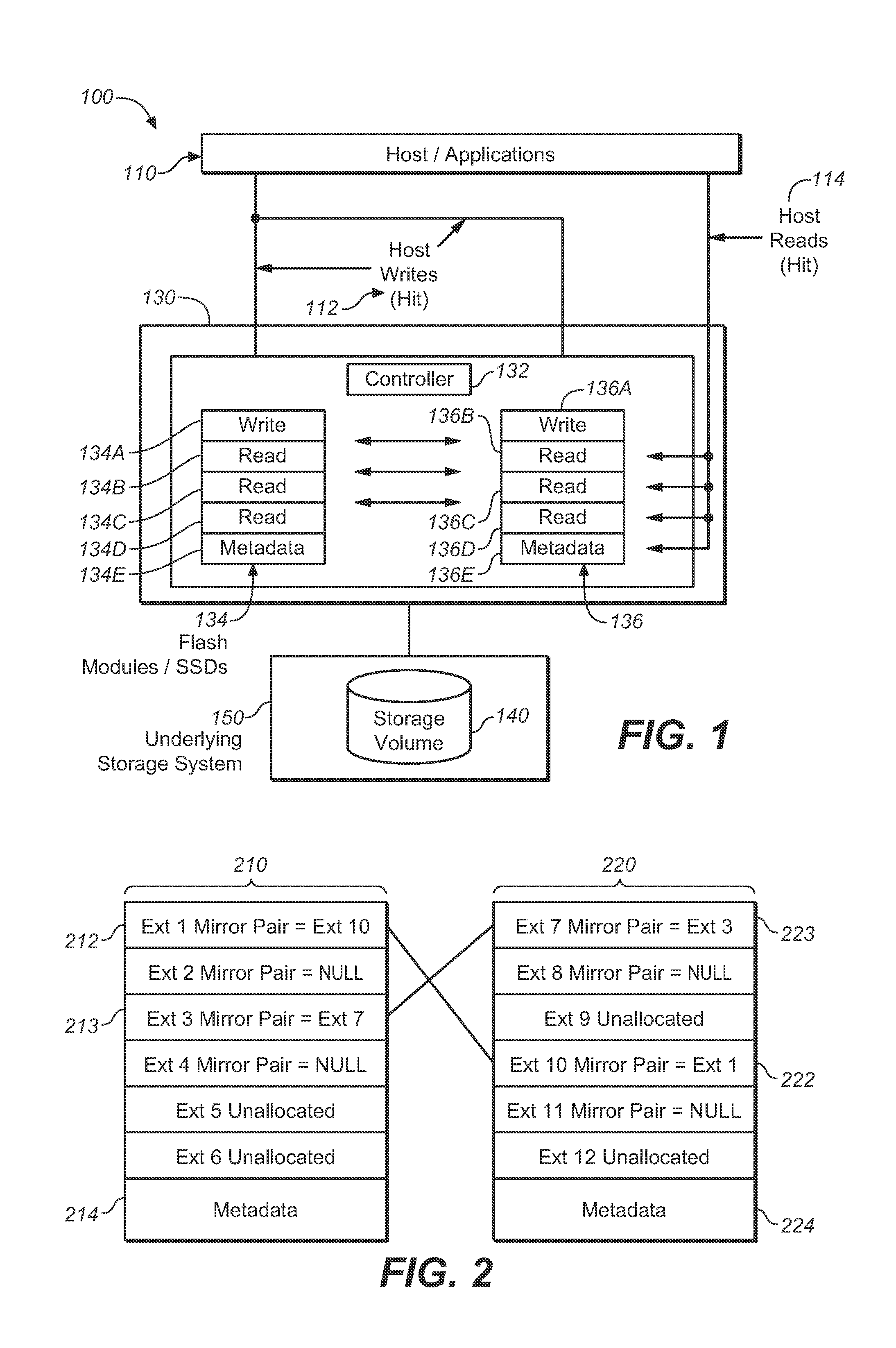
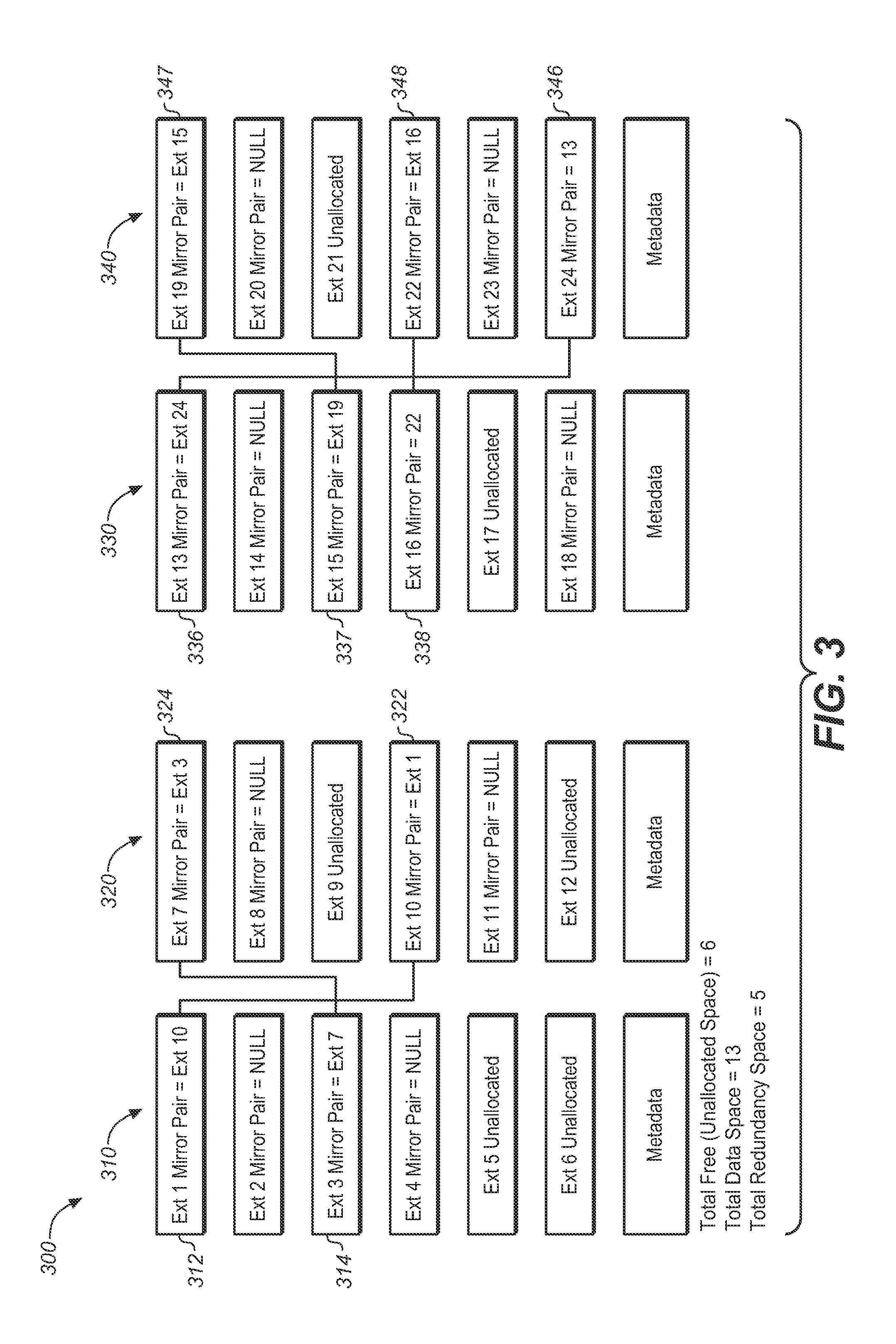
[0017]Embodiments of the invention may include a method for statically or dynamically converting a RAID 1 (or an elastic RAID 1) organization of cache data of a cache system to a RAID 5 organization of the cache data of the cache system. An elastic RAID 1 organization of cache data of a cache system provides benefit over a straight RAID 1 organization because the elastic RAID 1 organization only creates mirror pairs for dirty extents; whereas a straight RAID 1 organization creates mirror pairs for all extents. An extent represents a collecti...


PUM


Abstract

A method for managing redundancy of data in a solid-state cache system including at least three solid-state storage modules. The method may include designating one or more extents of each dirty mirror pair to be of a particular priority order of at least two priority orders. The at least two priority orders can include at least a highest priority order. The highest priority order can have a higher relative priority than the other priority orders. The method may also include performing at least one redundancy conversion iteration. Each redundancy conversion iteration includes converting extents of at least two dirty mirror pairs into at least one RAID 5 group and at least one unconverted extent. The extents of the at least two dirty mirror pairs can include extents designated to be of a highest remaining priority order. Each redundancy conversion iteration can also include deallocating the at least one unconverted extent.

Description


Claims


Application Information

Patent Timeline
Owner AVAGO TECH INT SALES PTE LTD
Why Eureka
Try Eureka