
Integrated torque coupling and mount

a torque coupling and integrated technology, applied in the direction of solar heat collector controllers, furniture joining, fastening means, etc., can solve the problems of manufacturing process challenges

Active Publication Date: 2014-04-03
SUNPOWER CORPORATION
View PDF23 Cites 29 Cited by
  • Summary
  • Abstract
  • Description
  • Claims
  • Application Information

AI Technical Summary

Benefits of technology

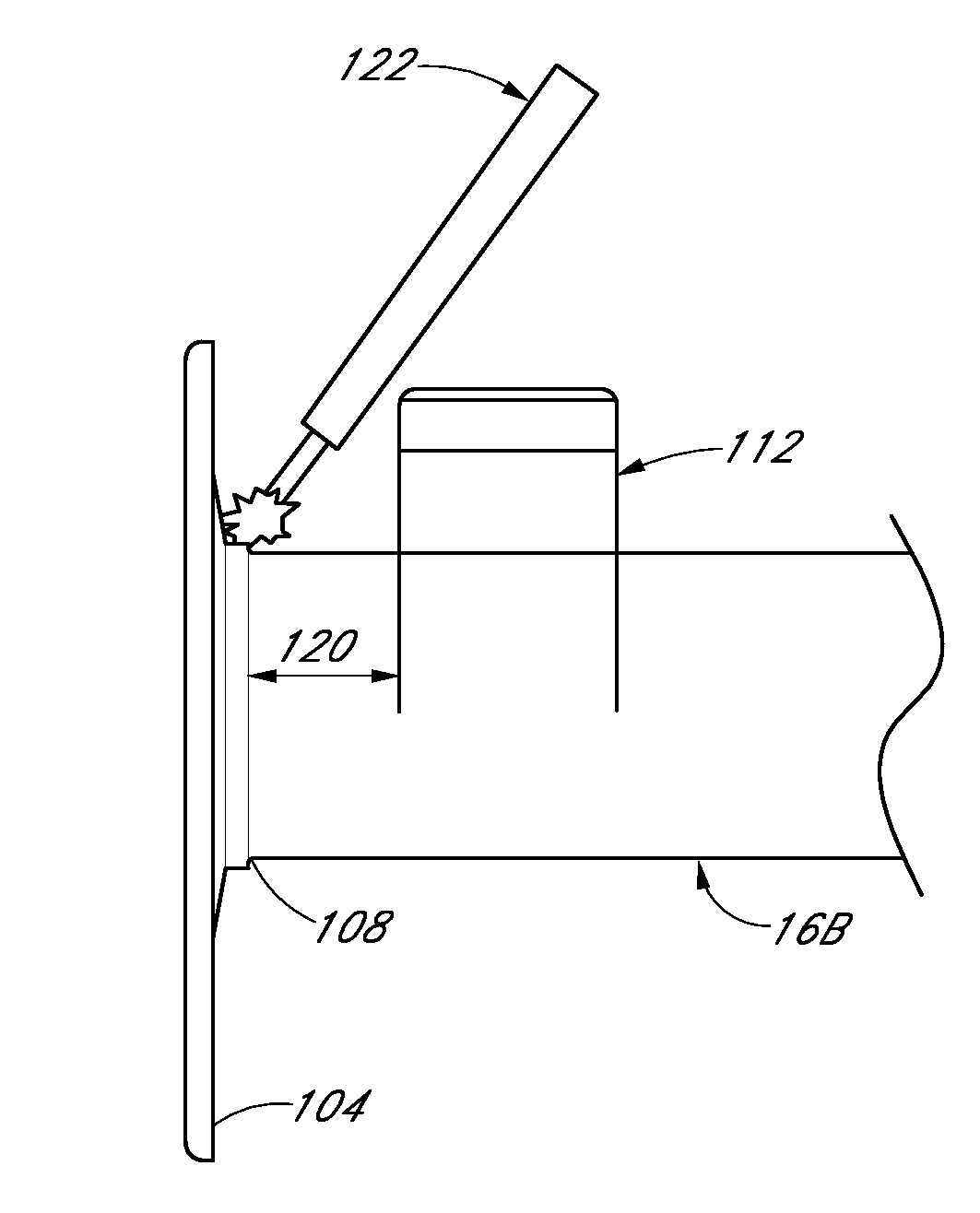
This invention aims to improve the efficiency of solar energy collection systems by reducing the gap between solar collection devices. Most current systems have gaps between the mounts of the photovoltaic modules and the torque tubes, which can be problematic during production. The solution is to integrate the photovoltaic module mount with the torque tube coupling flange, allowing for easier attachment without interfering with the photovoltaic modules. This results in a more effective and efficient solar energy collection system.

Problems solved by technology

For example, in some known systems, the photovoltaic module mounts located near coupling flanges, which are designed to transmit torque from one shaft (also known as “torque tube”) to the next sequential torque tube, can present challenges during the manufacturing process.

Method used


Image

  • Integrated torque coupling and mount
  • Integrated torque coupling and mount
  • Integrated torque coupling and mount

Examples


Embodiment Construction

[0023]The following detailed description is merely illustrative in nature and is not intended to limit the embodiments of the subject matter or the application and uses of such embodiments. As used herein, the word “exemplary” means “serving as an example, instance, or illustration.” Any implementation described herein as exemplary is not necessarily to be construed as preferred or advantageous over other implementations. Furthermore, there is no intention to be bound by any expressed or implied theory presented in the proceeding technical field, background, brief summary, or the following detailed description.

[0024]Certain terminology may be used in the following description for the purpose of reference only, and thus are not intended to be limiting. For example, terms such as “upper”, “lower”, “above”, and “below” refer to directions in the drawings to which reference is made. Terms such as “front”, “back”, “rear”, and “side” describe the orientation and / or location of portions of...


PUM

PropertyMeasurementUnit
Torqueaaaaaaaaaa

Abstract

A sun tracking solar energy collection system can include torque tubes formed with a plurality of rotatable shafts connected to each other in an end to end fashion. The ends of the shafts can be connected with coupling devices in the form of an integrated coupling flange and mounting devices. The coupling flange can include a mounting surface that extends generally parallel to the axis of rotation of the shaft. Additionally, the coupling flange can include a coupling face that extends generally perpendicular to the axis of rotation, so as to provide a mating face for an adjacent coupling flange to transmit torque from one shaft to another. The mounting flanges can be used to support devices such as solar energy collection devices including photovoltaic modules or other devices.

Description

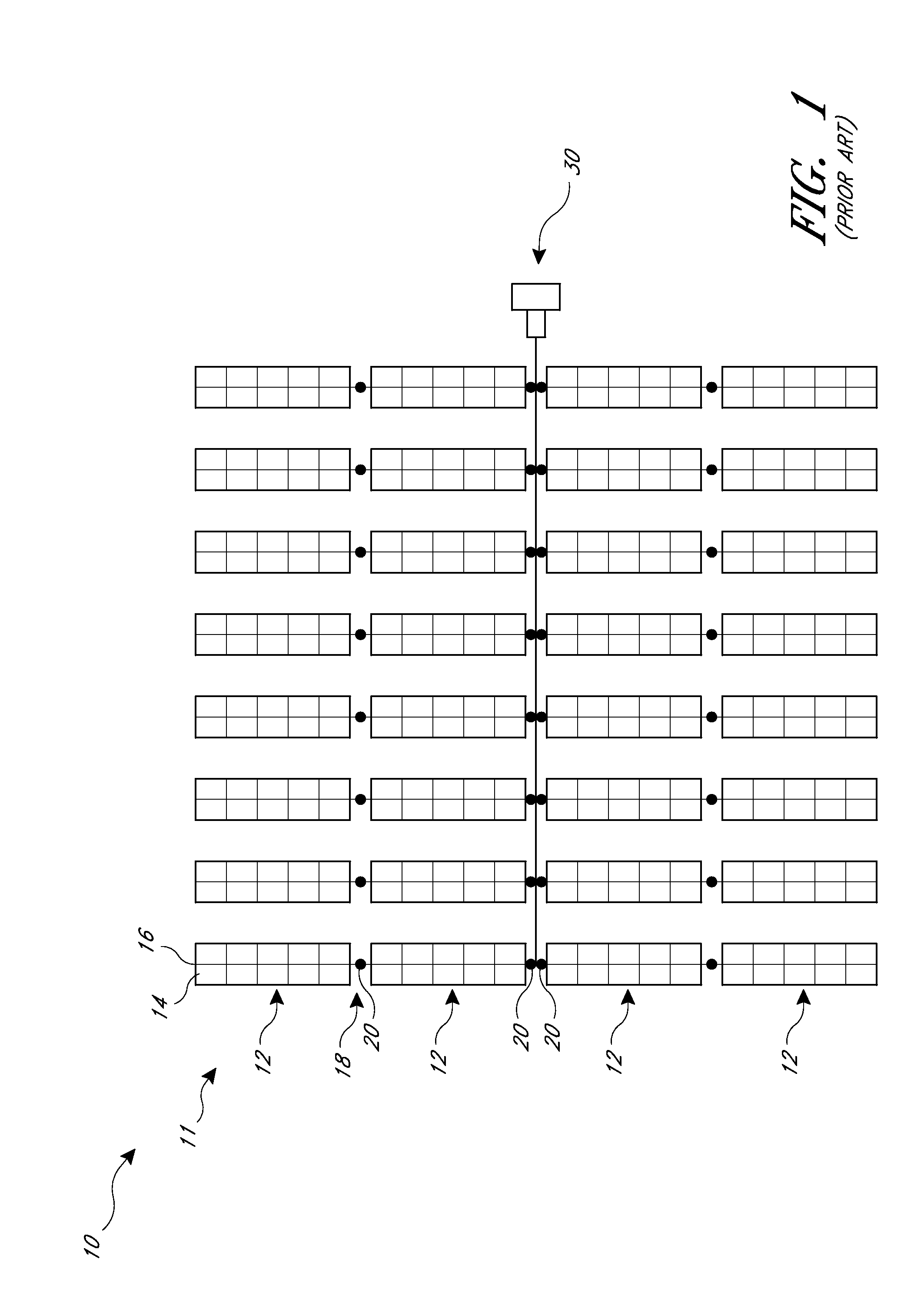
BACKGROUND OF THE INVENTIONS[0001]1. Field of the Inventions[0002]The present application is directed to connectors that can be used for various kinds of structures, including rotatable shafts, such as components for connecting shafts together and for mounting other devices to the shafts.[0003]2. Background[0004]Some known sun tracking photovoltaic solar power systems, such as utility-scale, photovoltaic installations, are designed to pivot a large number of solar modules so as to track the movement of the sun using the fewest possible number of driver motors. For example, some known systems include parallel rows of photovoltaic modules supported on torque tubes. The torque tubes can comprise a number of long shafts connected together in an end to end fashion. The torque tubes are supported in an orientation parallel to each other such that their pivot axes are parallel. These shafts are sufficiently long that they must be supported by many vertical columns, known as “piles”.[0005]I...

Claims


Application Information

Patent Timeline
IPC IPC(8): F24J2/54F16D1/02F16D1/027B23P11/00F24S10/80F24S50/20
CPCF24J2/541F16D1/027F16D1/02B23P11/00F24S25/65F24S30/425F16D1/033F16D1/068H02S10/00F24S2030/136F24S2025/014Y02E10/47Y02E10/50H02S20/30Y10T29/49355Y10T403/47F16B2200/50
Inventor GRUSHKOWITZ, TYLER
Owner SUNPOWER CORPORATION
Learn More