Rod-shortening tool

a technology of shortening tool and rod, which is applied in the field of tool for shortening rod, can solve the problems of uncontrollable twisting of the section of the rod that is to be cut to length, the risk of injuring the soft tissue of the patient, etc., and achieves the effect of positive effect on user friendliness

Inactive Publication Date: 2014-04-03
ULRIKH GMBKH & KO KG
View PDF19 Cites 1 Cited by
  • Summary
  • Abstract
  • Description
  • Claims
  • Application Information

AI Technical Summary

Benefits of technology

[0016]The invention furthermore comprises a method for producing an individually adapted implant by using a predetermined score line that is generated by a tool that includes at least one guide roller and a cutting element, where the cutting element is continuously reset and biased against the implant by a biasing unit. This method provides the advantage that the need is eliminated to reset the cutting element as the predetermined score line becomes deeper, which aspect has a positive effect on user friendliness.
[0017]An approach has furthermore been found especially advantageous in terms of manipulation whereby adjustment of an eccentric lever is used to adjust the tool between a release position suitable for inserting and removing the implant, and a tensioning position generating the predetermined score line. Operating the tool with an eccentric lever ensures that the applied force required to generate the predetermined score line is reduced since the lever action of the eccentric lever can be utilized.
[0018]It has furthermore been found advantageous to generate the predetermined score line on the implant by relative rotation between the implant and the tool. This enables the predetermined score line to be generated around the complete outer circumference of the implant, thereby facilitating cutting the implant to length and ensuring a clean end on the implant rod after shortening.
[0019]It has furthermore been found advantageous if the implant is shortened by a breaking aid provided on the tool after the predetermined score line has been generated. After the predetermined score line is generated, the implant can thus be removed from the tool and inserted into the breaking-aid hole. Following this, the implant can simply be snapped off at the predetermined score line and thereby sized to the desired length.

Problems solved by technology

However, this often results in the cut surface of the rod having sharp edges, with the result that there is a risk of injuring soft tissues of the patient.
There is also the danger that the section of the rod that is to be cut to length will twist uncontrolledly.

Method used


Image

  • Rod-shortening tool
  • Rod-shortening tool
  • Rod-shortening tool

Examples


Embodiment Construction

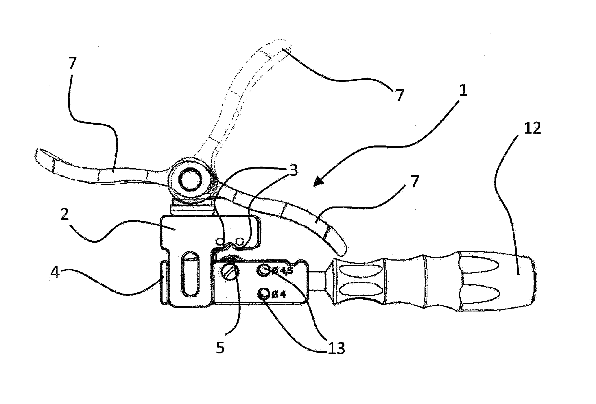
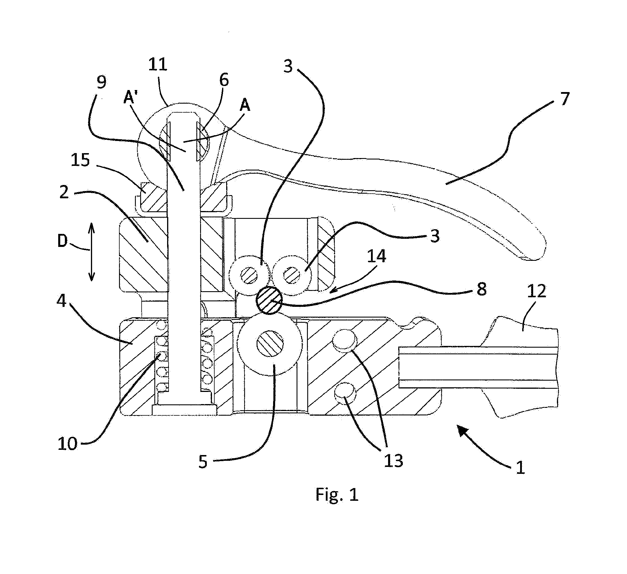
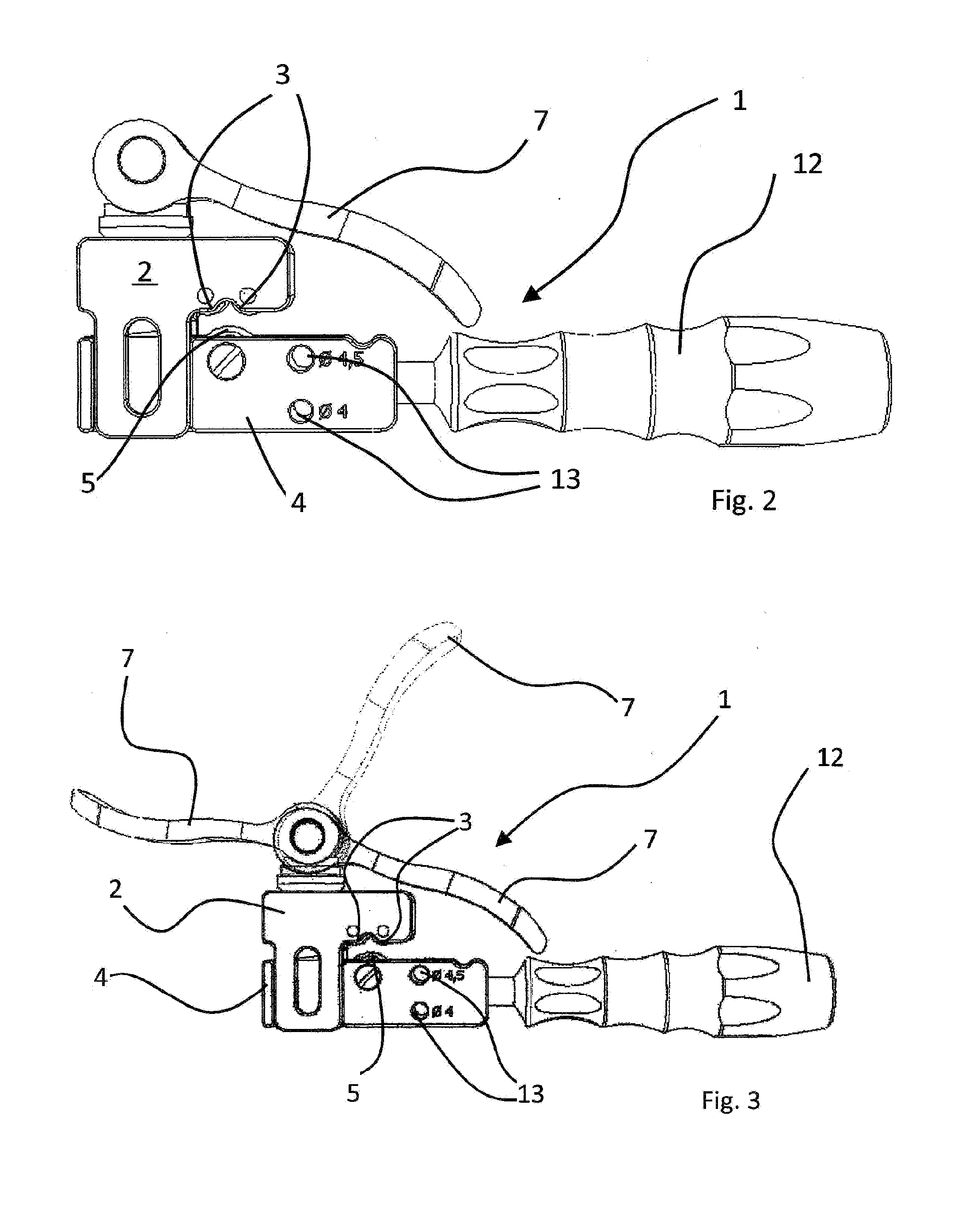
[0024]As seen in FIG. 1 a tool 1 for shortening an implant rod 8 by forming a score line in the rod 8. The tool 1 has a housing with a movable part 2 that carries two guide rollers 3 rotatable about respective parallel axes and a base part 4 in which is a cutter wheel 5 with a sharp edge is rotatable about an axis parallel to that of the guide rollers 3. The parts 2 and 4 can move limitedly relative to each other in a direction D to shift the roller 4 toward and away from the rollers 3.

[0025]A lever 7 is pivotal about an axis A relative to the housing 2, 4 and serves for shifting the parts 2 and 4 toward each other. To this end a pivot pin 6 on the axis is set in one end of the lever 7 and is coupled to a connecting rod 9 that extends in the direction D through the part 2 and mostly through the part 4. Inside the part 4 a tension spring 10 bears downward on a head of the rod 9 and upward on the part 4 so as to urge the two parts 2 and 4 together in the direction D. The one end of th...


PUM

PropertyMeasurementUnit
forceaaaaaaaaaa
spring forceaaaaaaaaaa
lengthaaaaaaaaaa

Abstract

A tool for shortening an implant rod has a base housing part and a movable housing part shiftable toward and away from each other in a predetermined direction. At least one guide roller is provided on the movable housing part, and a cutter is provided on the base housing part. The rod is fittable between the cutter and the guide roller in a spread position of the housing parts. A biasing unit urges the parts together and thereby presses the cutter into the rod with a predetermined force. Thus the cutter is pressed against the workpiece with a force that does not change and that is not under the control of the user, ensuring that the force applied lies within an acceptable safe range.

Description

FIELD OF THE INVENTION[0001]The present invention relates to tool for shortening a rod used in a spinal implant. More particularly this invention concerns method of and tool for doing this.BACKGROUND OF THE INVENTION[0002]Spinal surgery, in particular, entails the need to join multiple implants to each other. To this end, pedicle screws are inserted first into individual vertebrae and interconnected by a rod. To accomplish this, however, the length of the rod must be adapted to the specific requirements of the patient. As a result, it is thus necessary to shorten the rod to the appropriate length. This is generally done using ordinary pliers to cut to length the rod that is to be shorted. However, this often results in the cut surface of the rod having sharp edges, with the result that there is a risk of injuring soft tissues of the patient. There is also the danger that the section of the rod that is to be cut to length will twist uncontrolledly.OBJECTS OF THE INVENTION[0003]It is ...

Claims


Application Information

Patent Timeline
Patent Type & Authority Applications(United States)
IPC IPC(8): A61B17/88B26F3/00B26D3/08
CPCA61B17/8863B26F3/002B26D3/08A61B17/7002B23D21/08B23D31/002Y10T83/0341Y10T225/12Y10T225/321
Inventor DIRR, STEFFEN
Owner ULRIKH GMBKH & KO KG
Why Eureka
Try Eureka