Image Forming Apparatus

Active Publication Date: 2014-04-03
BROTHER KOGYO KK
View PDF1 Cites 3 Cited by
  • Summary
  • Abstract
  • Description
  • Claims
  • Application Information

AI Technical Summary

Benefits of technology

[0010]In the image forming apparatus according to aspects of the invention, a frame is arranged to face the sheet placing part. The frame is configured to support the supply roller and has a protruded part, which protrudes, in a sheet feed direction in which the sheet is supplied toward the sheet feed path, on the opening side with respect to the supply roller. Further, on a surface of the protruded part, facing the sheet placing part, an inclined surface is formed. The inclined surface is configur

Problems solved by technology

Therefore, in such an image forming apparatus, a leading end of the sheet may contact the suppl

Method used


Image

  • Image Forming Apparatus
  • Image Forming Apparatus
  • Image Forming Apparatus

Examples


Embodiment Construction

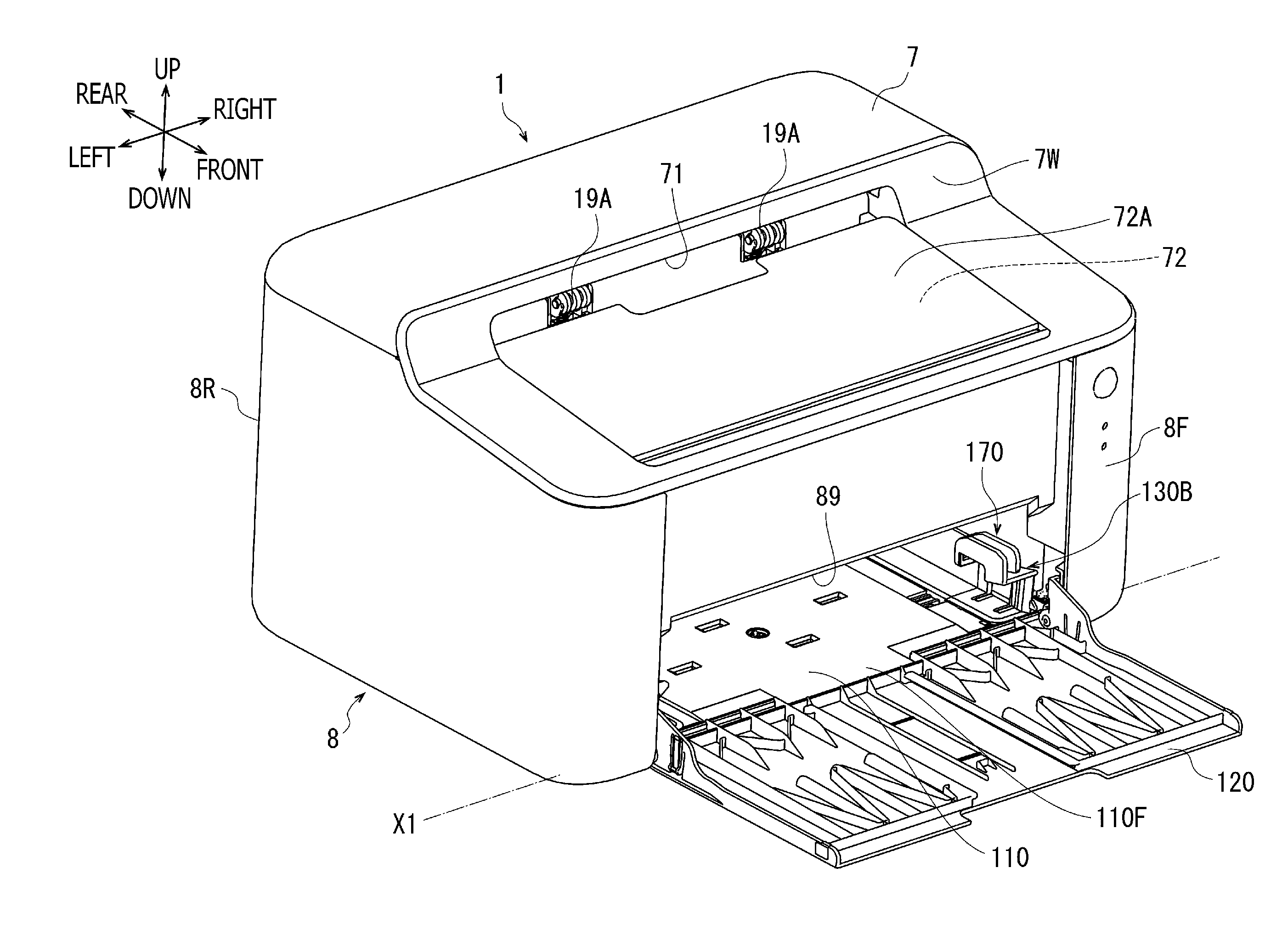
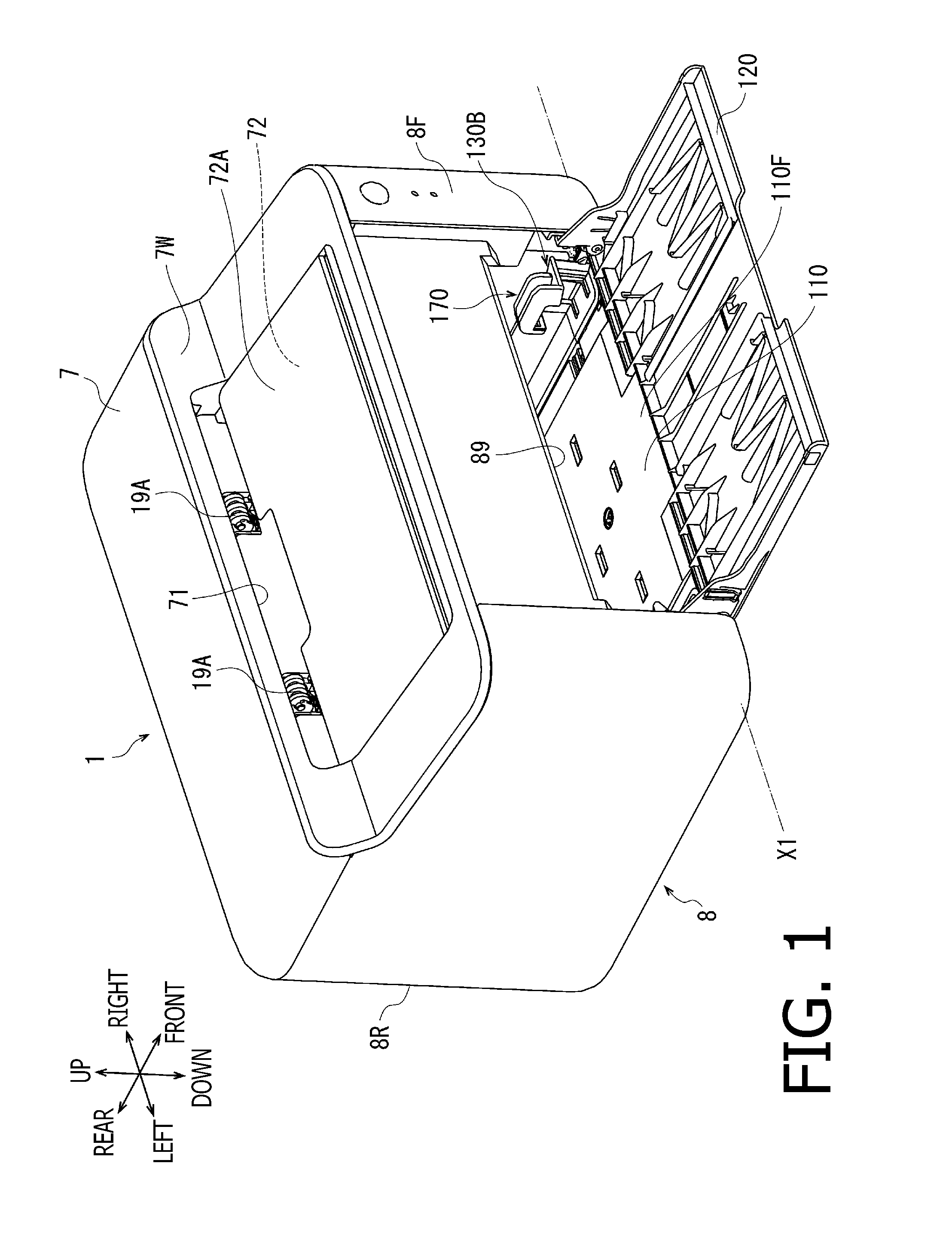
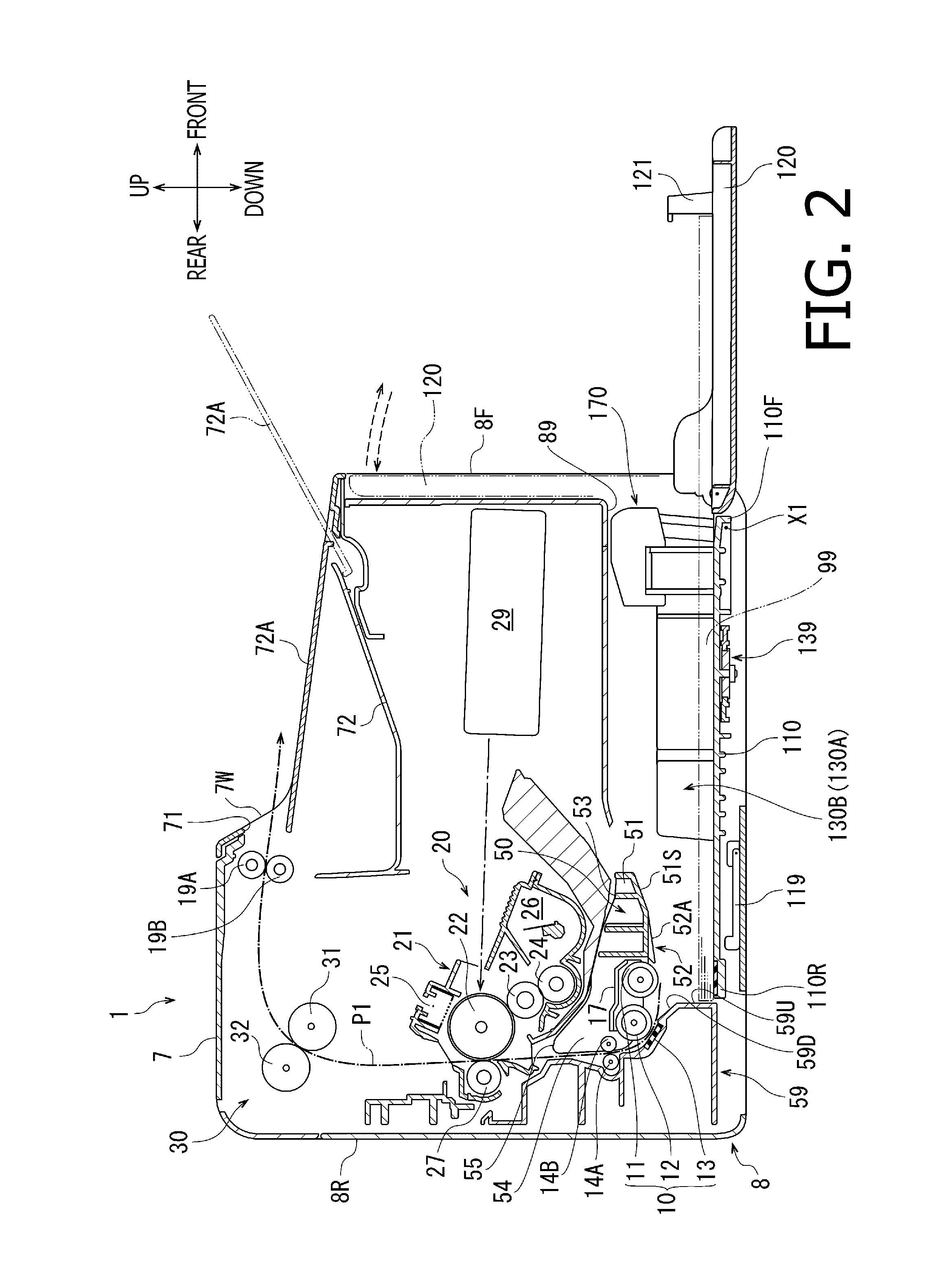
[0022]Hereinafter, an exemplary embodiment will be described, referring to the drawings.

[0023]An image forming apparatus 1 shown in FIG. 1 is an exemplary embodiment of the present invention. In FIG. 1, a side of the image forming apparatus 1 where an opening 89 is formed is defined as a front side of the image forming apparatus 1. Facing the opening 89, a left-hand side of the image forming apparatus 1 is defined as a left-side of the image forming apparatus 1. The other directions are defined similarly and are indicated in FIG. 1 and the other drawings.

[0024]

[0025]The image forming apparatus 1 is a monochrome laser printer. As shown in FIGS. 1 and 2, the image forming apparatus 1 has a main body 8, a sheet feed unit 10, a drive roller 14A, a pinch roller 14B, a feeding unit holding frame 50, a movable (openable / closable) tray 120, a platen 110, side guides 130A and 130B, an image forming unit 20, a pair of ejection rollers 19A and 19B.

[0026]The main body 8 has a substantially box-...


PUM

PropertyMeasurementUnit
Widthaaaaaaaaaa

Abstract

An image forming apparatus has a main body having a sheet feed path and an opening. A sheet placing part defined in the main body. The sheet inserted through the opening is placed on the sheet placing part. A supply roller arranged to face the placing part and feeds the sheet placed on the sheet placing part in a sheet feed direction toward the sheet feed path, a frame arranged to face the sheet placing part and configured to support the supply roller, the frame having a protruded part protruded on an opening side with respect to the supply roller. An image forming unit is provided inside the main body. An inclined surface is formed on a side of the protruded part facing the sheet placing part, and the protruded part has an inclined surface facing the sheet placing part and inclined such that a distance between the inclined surface and the sheet placing part becomes gradually smaller toward the supply roller.

Description

CROSS-REFERENCE TO RELATED APPLICATION[0001]This application claims priority under 35 U.S.C. §119 from Japanese Patent Application No. 2012-216676 filed on Sep. 28, 2012. The entire subject matter of the application is incorporated herein by reference.BACKGROUND[0002]1. Technical Field[0003]Aspects of the present invention relate to an image forming apparatus.[0004]2. Prior Art[0005]A conventional image forming apparatus typically has a main body, a sheet placing part, a sheet supply roller and an image forming unit. In the main body, a sheet feed path through which a sheet is fed is formed. On the main body, an opening through which inside and outside of the image forming apparatus communicate. The sheet placing part is defined inside the main body, and sheets, which are inserted in the main body are placed thereon. The sheet ejection roller is arranged at a position opposing to the sheet placing part, and feeds the sheets placed on the sheet placing part toward the sheet feed path...

Claims


Application Information

Patent Timeline
IPC IPC(8): B65H5/06
CPCB65H5/062B41J13/103B65H1/04B65H3/0607B65H3/0684B65H3/68B65H31/02B65H2301/4212B65H2402/46B65H2404/14211B65H2405/1117B65H2405/324B65H2405/3322B65H2801/12G03G15/14G03G15/6511
Inventor UEYAMA, JUNKI
Owner BROTHER KOGYO KK
Why Eureka
Try Eureka