Suspension for vehicle

Active Publication Date: 2014-04-03
NSK LTD
View PDF1 Cites 8 Cited by
  • Summary
  • Abstract
  • Description
  • Claims
  • Application Information

AI Technical Summary

Benefits of technology

[0030]With the present invention constructed as described above, it is possible to achieve a suspension for a vehicle with simple construction that is capable of suitably changing the camber angle according to the traveling conditions of the vehicle, and it is possible to make the overall suspension more compact and lightweight. In other words, in the case of the suspension for a vehicle of the present invention, construction for making it possible to change the overall length of the upper arm (length of the link arms in the width direction of the vehicle) is consolidated in the upper arm itself. Therefore, the other members, such as the lower arm, can be the same as used in the conventional construction. Moreover, there is no need to install members such as a hydraulic pump on the vehicle side (for example, the engine room) as was required in the second example of conventional construction. Furthermore, the upper arm is such that by using simple construction of just combining a pair of feed screw mechanisms, a

Problems solved by technology

However, even in the case of the apparatuses disclosed in these patent literatures, as in the case of the apparatus disclosed in JP 10-263636 (A), there is a

Method used


Image

  • Suspension for vehicle
  • Suspension for vehicle
  • Suspension for vehicle

Examples


example 1

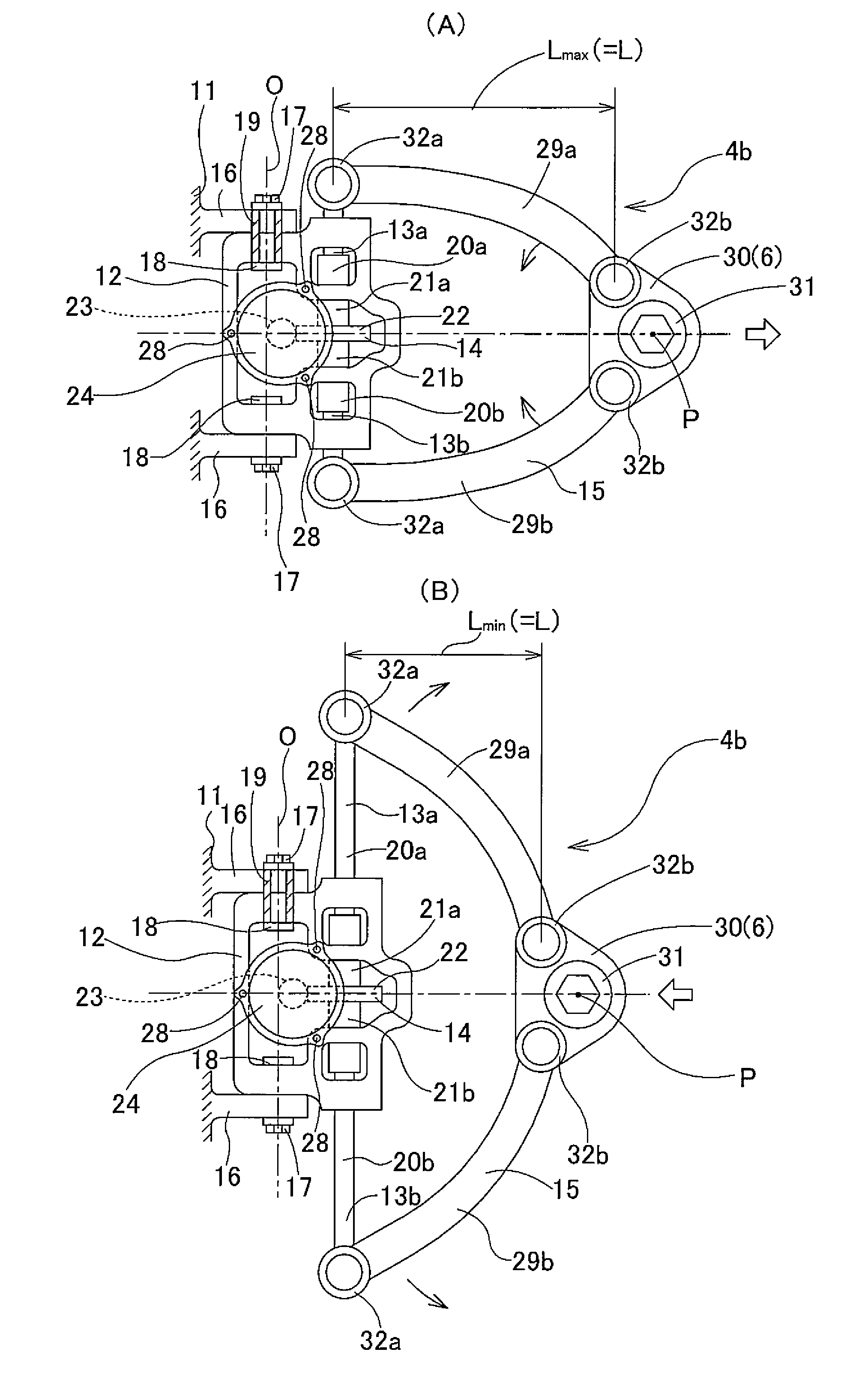
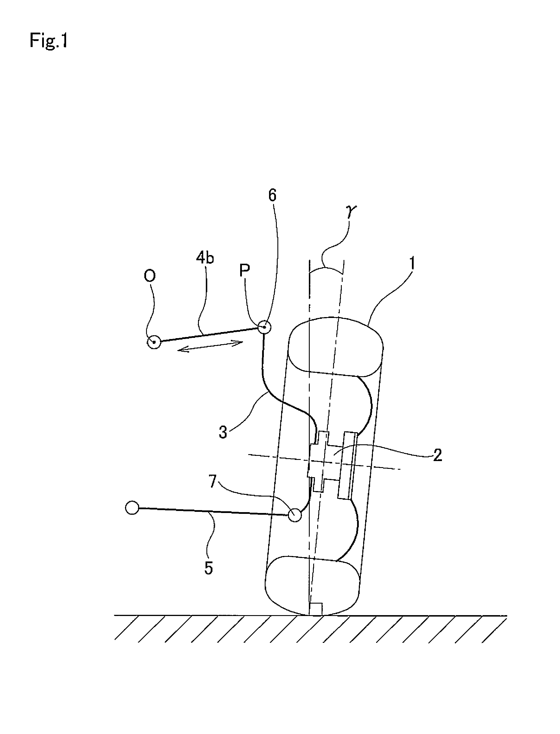
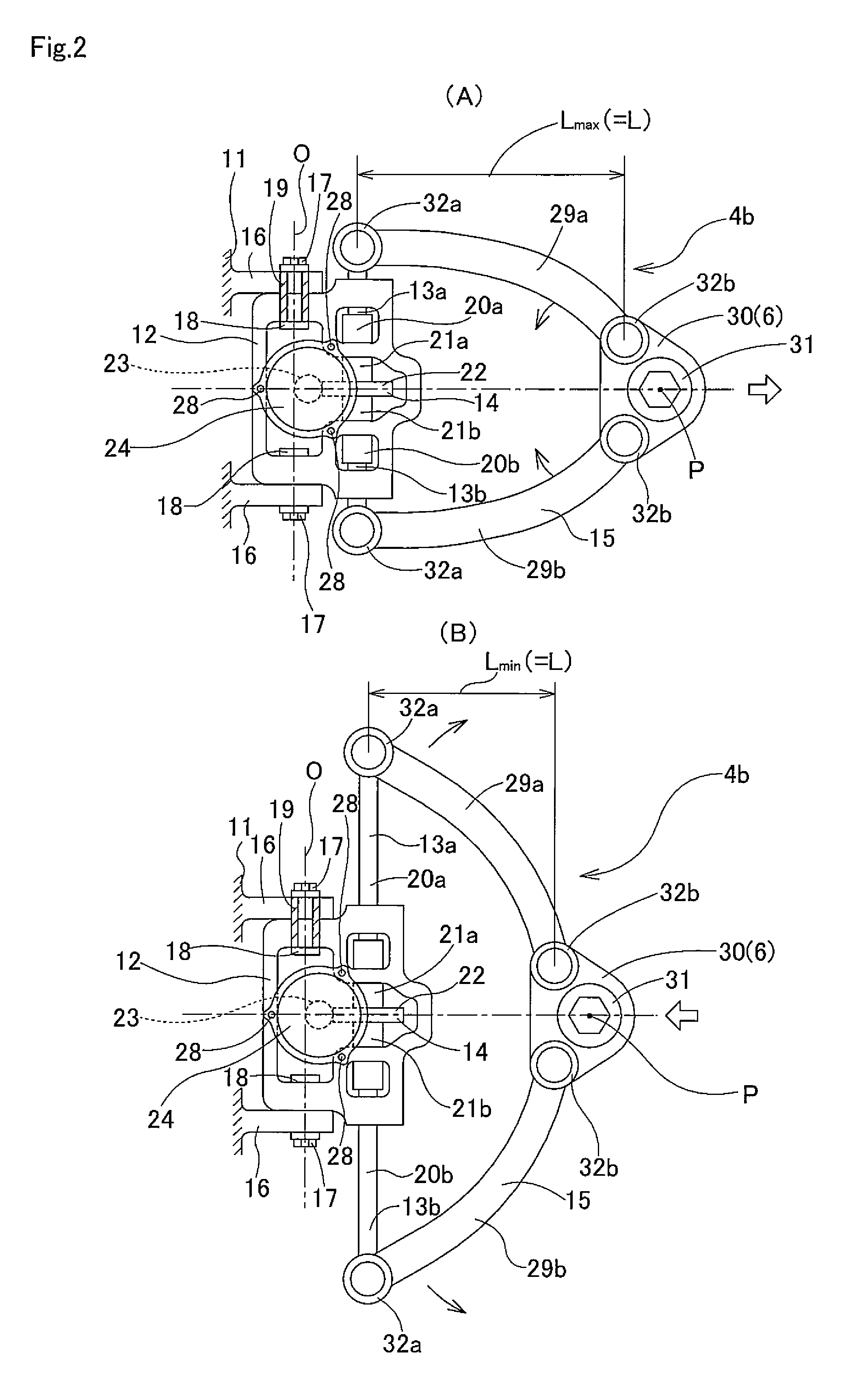
[0038]FIG. 1 to FIG. 3 illustrate an example of an embodiment of the present invention. A feature of this example is making it possible to suitably change the camber angle γ according to the traveling conditions of a vehicle by consolidating construction for making it possible to change the overall length of the upper arm 4b in the upper arm 4b itself of a double wishbone suspension of a vehicle. The lower arm 5 and other members are the same as in the first example of conventional construction illustrated in FIG. 4. Therefore, the explanation below will center on the construction of the upper arm 4b, which is the feature of this example.

[0039]As illustrated in FIG. 1, even in the case of the suspension for a vehicle of this example, the knuckle 3, which supports the wheel 1 by way of a bearing unit 2 so as to be able to rotate, is supported by the vehicle 11 (see FIG. 2) by way of the upper arm 4b and lower arm 5 so as to be able to pivot. In order for this, the tip end section (ri...


PUM


Abstract

A upper arm 4b of a suspension for a vehicle is constructed by: a casing 12 that is supported by the vehicle so as to be able to pivot in the up-down direction; a pair of screw shafts 20 that are supported by the casing 12 so as to be able to move only in the axial direction; a pair of screw nuts 21 that engage around the pair of screw shafts 20, and are supported by the casing so as only to be able to rotate; a worm reduction gear 14 that rotates the screw nuts 21; and a pair of link arms 29, where the base end sections respectively connect to the tip end sections of the pair of screw shafts 20 and the tip end sections respectively connect to knuckle 3 so as to be able to rotate around a shaft in the up-down direction of the vehicle. The screw shafts 20 are moved out in opposite directions from each other in the axial direction, which causes the opening angle of the pair of link arms 29a to change, and thus changes the overall length of the upper arm 4b in the width direction of the vehicle.

Description

TECHNICAL FIELD[0001]The present invention relates to a double wishbone suspension for a vehicle that can suitably change the camber angle according to the traveling condition of the vehicle.BACKGROUND ART[0002]Various kinds of construction for a suspension for a vehicle such as an automobile are known. Recently, a double wishbone suspension, which has a high degree of design freedom and has excellent road surface followability, is used in many kinds of automobiles such as luxury automobiles and sports cars. FIG. 4 illustrates a first example of conventional construction of a double wishbone suspension that is disclosed in “Illustrated Book of Car Mechanisms and Structures” (Hosokawa, Takeshi; Grand Prix Book Publishing Co., Ltd.; Jan. 10, 2003; pg. 207).[0003]A knuckle 3, which supports a wheel 1 by way of a bearing unit 2 so as to be able to rotate, is supported by the vehicle (not illustrated in the figure) by an upper arm 4 and a lower arm 5 of a double wishbone suspension so as...

Claims


Application Information

Patent Timeline
IPC IPC(8): B60G7/00
CPCB60G7/006B60G17/0162B60G2200/46B60G2202/40B60G2202/442B60G2204/143
Inventor MATSUDA, YASUYUKIGUNJI, DAISUKE
Owner NSK LTD
Why Eureka
Try Eureka