Sun visor for a vehicle

a technology for sun visors and vehicles, applied in the direction of roofs, superstructures, monocoque constructions, etc., can solve the problems of high risk of injury, uncontrolled manner into a plurality of parts, and the risk of vehicle occupants being injured by vehicle fitting parts, etc., to avoid damage to the counter fastening means

Inactive Publication Date: 2014-04-03
JOHNSON CONTROLS TECH CO
View PDF2 Cites 4 Cited by
  • Summary
  • Abstract
  • Description
  • Claims
  • Application Information

AI Technical Summary

Benefits of technology

[0010]Provision is made, according to a further preferred embodiment of the present invention, for the visor body to have a cutout along the main direction of extent of the cylindrical spindle between the weakened region and the further weakened region. The cutout makes it possible for a counter fastening means which is mounted on the vehicle and in particular is fitted to the roof lining to at least partially engage around the exposed region of the cylindrical spindle, thus enabling the sun visor to be fastened to the vehicle and in particular to the roof lining. The counter fastening means comprises, in particular, a clamping claw with or without a recess, wherein the exposed region of the cylindrical spindle is clampable into the recess.
[0011]Owing to the further weakened region, the weakened region advantageously acts as a hinge when an external force, for example in the event of an accident, acts on the cylindrical spindle in the region of the exposed region, and therefore the end sides of the cylindrical partial spindles move counter to each other perpendicularly to the main direction of extent of the cylindrical spindle and the cylindrical spindle is bent around the weakened region and in particular around the region having a reduced cross section or the notch in the outer surface area. Splitting of the visor body itself or damage to the counter fastening means is therefore avoided.

Problems solved by technology

In principle, any vehicle fitting parts which are arranged in the vehicle interior involve the risk of a vehicle occupant being injured by such vehicle fitting parts in the event of an accident.
A particularly high risk of injury here emanates from vehicle fitting parts which, in the event of being acted upon by a force, split in an uncontrolled manner into a plurality of parts.
This is because this may create splinters which can move freely in the vehicle interior and therefore, for example, can get into the eyes of a vehicle occupant in a health-endangering manner.
Furthermore, it is conceivable that an uncontrolled splitting may produce fragments having comparatively sharp broken edges, thus increasing the risk of cutting injuries for vehicle occupants.

Method used


Image

  • Sun visor for a vehicle
  • Sun visor for a vehicle

Examples


Embodiment Construction

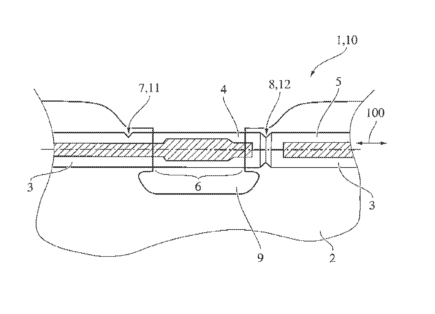
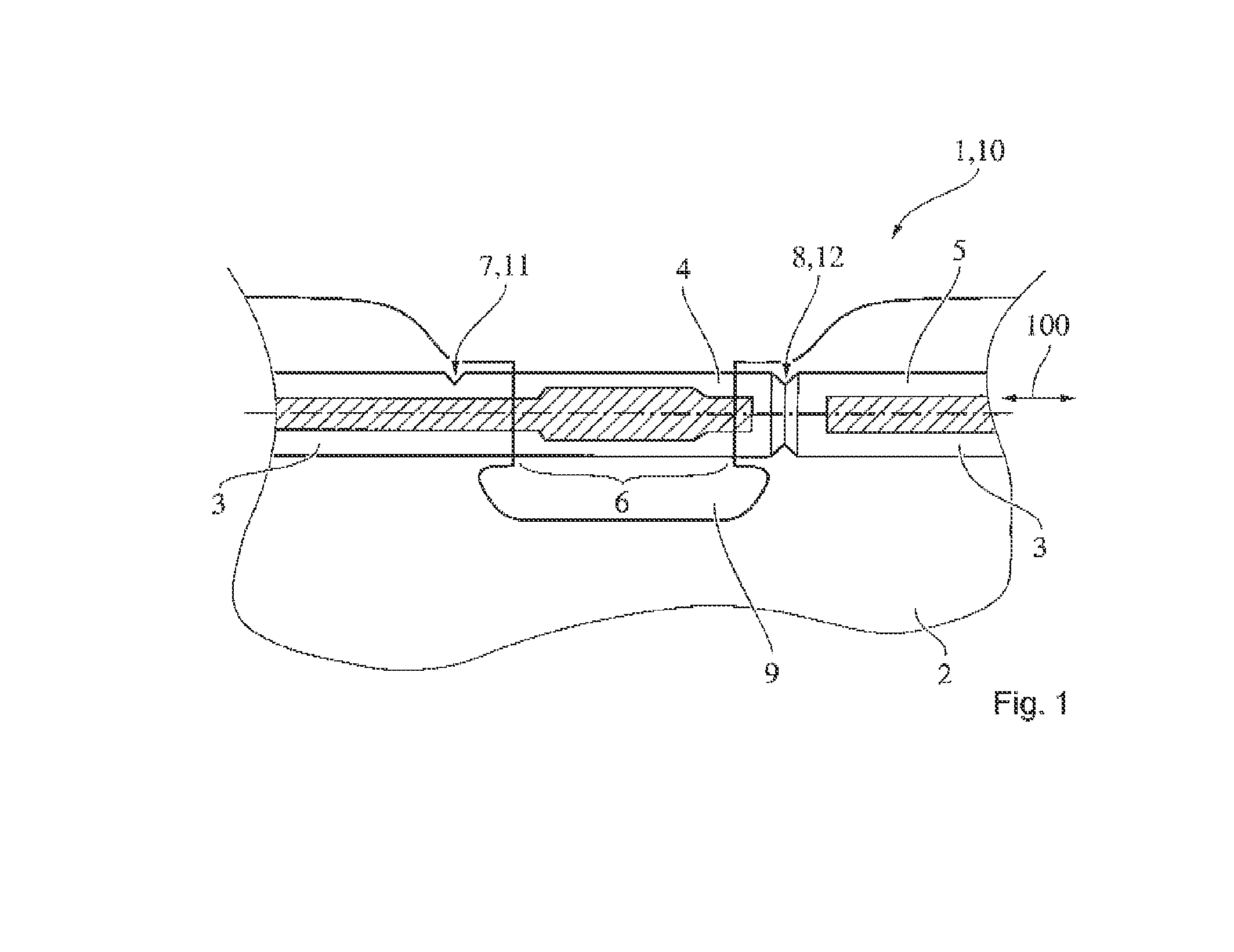
[0014]The excerpt illustrated in FIG. 1 shows a fastening region 10 of a sun visor 1 for a vehicle. The sun visor 1 comprises a visor body 2 which is provided with a cutout 9. A cylindrical spindle 3 which is encased outside the cutout 9 by the material of the visor body 2 and is exposed in the region of the cutout 9, i.e. is not encased by the material of the visor body 2, extends through the visor body 2. Said exposed region of the cylindrical spindle 3 is provided for clamping into a counter fastening means (not illustrated) which is mounted on a roof lining of the vehicle. The counter fastening means comprises, for example, a clamping claw with, or without, a recess which is open on one side and into which the exposed region 6 is clampable in a frictional and interlocking manner. The exposed region 6 is clamped in the recess, for example, by means of a leaf spring which is pretensioned in the direction of the surface area of the exposed region 6.

[0015]The sun visor 1 has, in the...


PUM


Abstract

The invention relates to a sun visor for a vehicle which has a visor body and a fastening region, wherein the fastening region is for fastening the visor body to a counterpart attached to a vehicle.

Description

PRIOR ART[0001]Sun visors for vehicles are generally known. They are customarily fitted to a roof lining in the vicinity of a transition region between a windshield and the roof lining in the interior of a passenger cell. In a non-use position, such sun visors extend substantially in a horizontal position parallel to the roof lining and can be folded from the roof lining in the direction of the wind shield at least partially into the field of view of a vehicle occupant, i.e. into a use position, in order to protect the vehicle occupant against solar radiation shining in from the outside. This is intended in particular to prevent the vehicle occupant from being dazzled by solar radiation and the occupant's view of the carriageway and the traffic being impaired as a result.[0002]In principle, any vehicle fitting parts which are arranged in the vehicle interior involve the risk of a vehicle occupant being injured by such vehicle fitting parts in the event of an accident. It is therefor...

Claims


Application Information

Patent Timeline
Patent Type & Authority Applications(United States)
IPC IPC(8): B60J3/02
CPCB60J3/0265B60J3/023B60J3/02
Inventor DOLISY, JACKY
Owner JOHNSON CONTROLS TECH CO
Why Eureka
Try Eureka