
Head-up display system with dynamic image field and brightness control

a display system and dynamic image technology, applied in the field of head-up display systems with dynamic image field and brightness control, can solve the problems of minimally distorted images, increased magnification, and inability to display sun load conditions, etc., to achieve high brightness, increase or decrease the size of the display, and high resolution

Inactive Publication Date: 2014-04-03
DELPHI TECH INC
View PDF2 Cites 20 Cited by
  • Summary
  • Abstract
  • Description
  • Claims
  • Application Information

AI Technical Summary

Benefits of technology

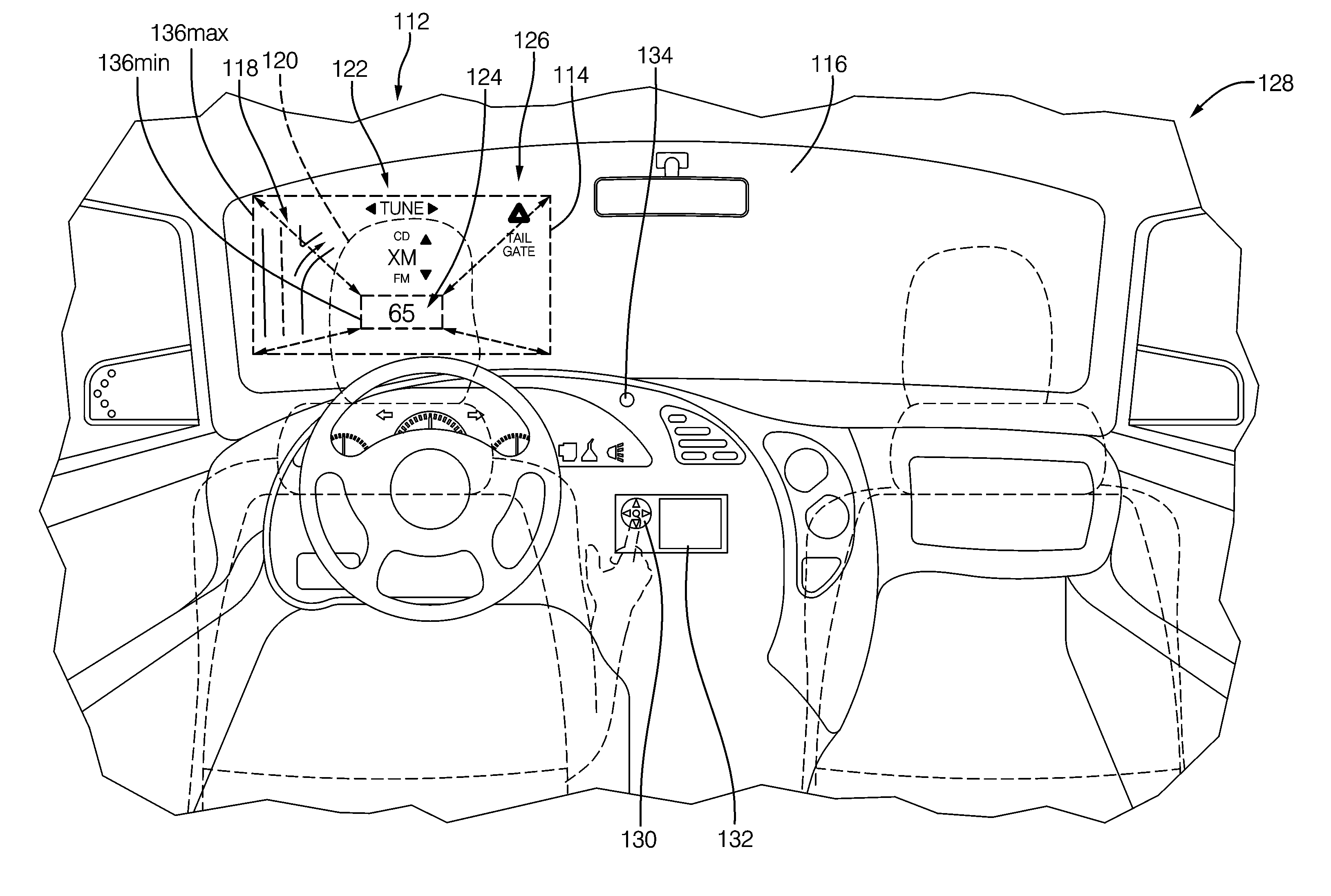
The present invention is a high resolution and brightness color head-up display (HUD) for the automotive market. It uses a collimated light source to adjust the size and brightness of the image field within the driver's field of view (FOV). The invention allows the driver to select how much information is provided, where it is located, and how bright the display should be. This overcomes the shortcomings of fixed image size in known HUD systems. The invention can accommodate night vision systems within the same package, providing a larger image field in the FOV. It also allows for a smaller, brighter image for day-time use and a larger, muted image for night-time use. The invention provides a dynamic image size that enables the driver to determine how much information or situational awareness indicators are presented. It can be used for other display applications such as instrument clusters and infotainment displays.

Problems solved by technology

Unfortunately, the image source size is desired to be as small as possible to reduce cost of the image source and associated packaging.
As image sources become smaller, the optical system needs to increase magnification and is challenged in producing a minimally distorted image.
The magnification increase can produce an unacceptable sun load condition presented to the image source as well.
Should the magnification of the optical system be high enough to produce an excessive sun load condition, the image source will be damaged.
Optical system performance also suffers in conventional systems when using small image sources.
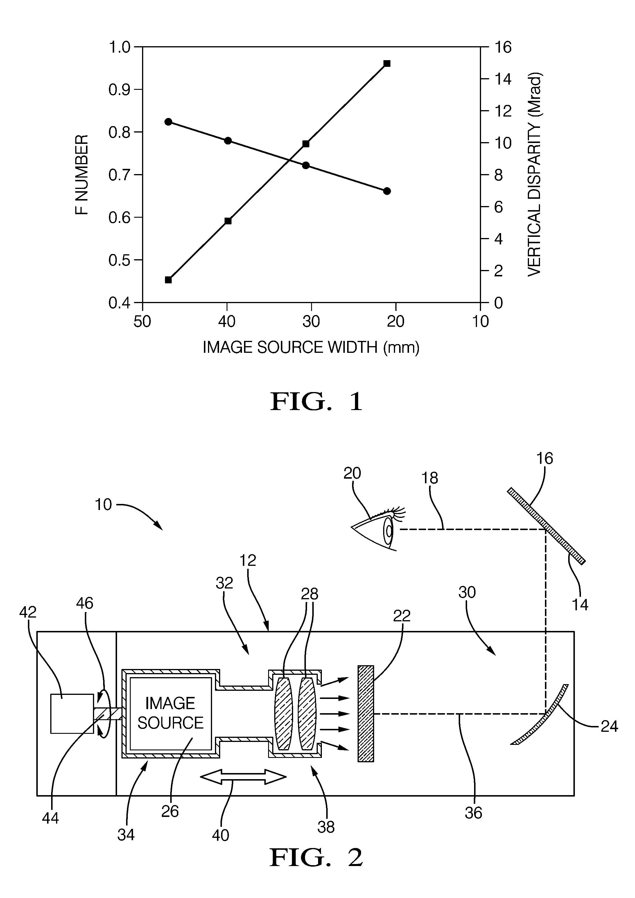
As can be seen in FIG. 1, as the image width drops below 50 mm, the vertical disparity error increases quite rapidly.
A cost penalty is now realized due to the inability to use smaller than 50 mm wide image sources (for this example).

Method used


Image

  • Head-up display system with dynamic image field and brightness control
  • Head-up display system with dynamic image field and brightness control
  • Head-up display system with dynamic image field and brightness control

Examples


first embodiment

[0022]Referring to FIG. 2, a schematic view of a head-up display system 10 is illustrated. Head-up display system 10 has a head-up display module 12 configured for installation in a passenger vehicle and positioned to reflect an image off a surface 14 of a vehicle windshield 16 into the line-of-sight 18 of a vehicle operator or passenger 20.

[0023]When a large image field is desired, or the performance and sun load characteristics are unacceptable, a diffuser 22 or diffusing image plane may be employed in accordance with the present invention.

[0024]The diffusing image plane head-up display system 10 comprises a windshield 16 which is viewed by the driver 20 and a curved or focusing mirror 24 disposed to focus an image on the windshield 16. The diffuser 22 is disposed between the mirror 24 and an image or display source 26 substantially at a focus of the mirror 24. Imaging optics 28 are disposed between the diffuser 22 and the image source 26 that image the output of the image source ...

second embodiment

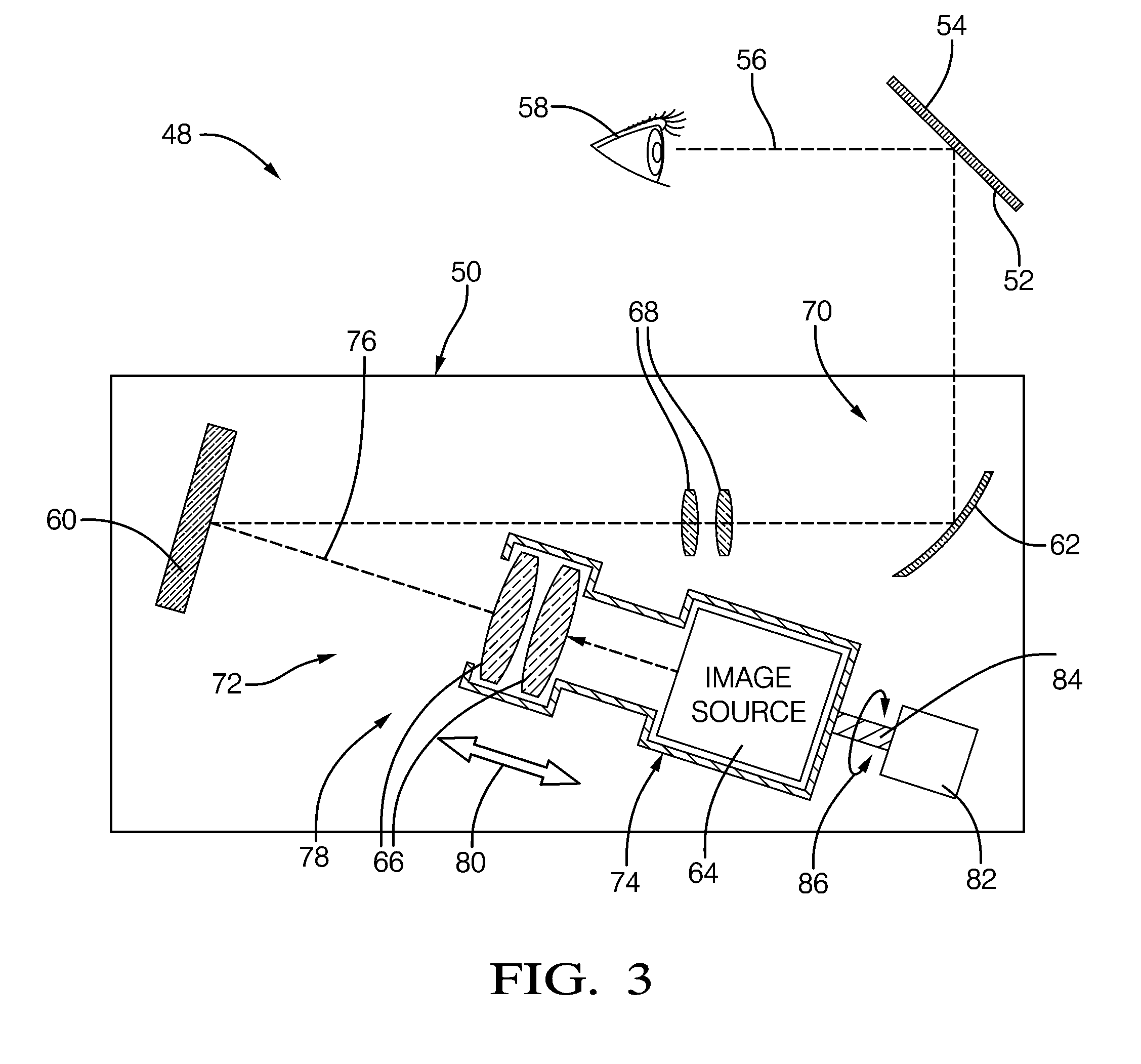
[0028]Referring to FIG. 3, a schematic view of a head-up display system 48 is illustrated. Head-up display system 48 has a head-up display module 50 configured for installation in a passenger vehicle and positioned to reflect an image off a surface 52 of a vehicle windshield 54 into the line-of-sight 56 of a vehicle operator or passenger 58.

[0029]The diffusing image plane head-up display system 48 comprises a windshield 54 which is viewed by the driver 58 and a curved or focusing mirror 62 disposed to focus an image on the windshield 54. The diffuser 60 is disposed between the mirror 62 and an image or display source 64 substantially at a focus of the mirror 62. Imaging optics 66 are disposed between the diffuser 60 and the image source 64 that image the output of the image source 64 onto the diffuser 60. In addition, application optics 68 may be disposed between the diffuser 60 and the mirror 62, as required, for a particular vehicle application, to address specific imaging require...


PUM


Abstract

A head-up display system having a diffusing image plane or diffuser. The light output of a relatively small image source is imaged on the diffuser by way of imaging optics. A mirror is used to image light from the diffuser onto a windshield and correct for distortion caused by the windshield. The diffuser is advantageously used when a large field-of-view is desired, or sun load characteristics need to be addressed. The diffuser may be flat or curved in order to optimize the system for different applications. The magnification of the mirror may be made relatively low, and the solar emergency density that is made incident on the image source is reduced, providing for a low cost, high performance, color head-up display system. A drive mechanism allows selective operator controlled repositioning of the image source and imaging optics with respect to diffuser to vary image size, position and / or intensity.

Description

TECHNICAL FIELD[0001]The present invention generally relates to head-up display (HUD) systems, and more particularly relates to an automotive windshield projection HUD system capable of dynamically changing the projected image.BACKGROUND OF THE INVENTION[0002]As the design intent image field of a head-up display projected within a vehicle operator's field-of-view (FOV) increases, the size of the image source tends to increase in order to keep a lower optical system magnification. Unfortunately, the image source size is desired to be as small as possible to reduce cost of the image source and associated packaging.[0003]As image sources become smaller, the optical system needs to increase magnification and is challenged in producing a minimally distorted image. The magnification increase can produce an unacceptable sun load condition presented to the image source as well.[0004]Sun load is a calculated energy irradiance value expressed in watts / cm2. The heating of the image source is d...

Claims


Application Information

Patent Timeline
Patent Type & Authority Applications(United States)
IPC IPC(8): G02B27/01
CPCG02B5/02G02B27/0101G02B2027/0116G02B2027/0123G02B2027/015
Inventor HUDSON, MARK W.
Owner DELPHI TECH INC
Learn More