Skin Marking Porous Grid and Related Method of Use

a skin marking and porous grid technology, applied in the field of skin marking porous grids, can solve the problems of impeded accuracy of placement of marks, underlying surface cannot be marked substantially any point, and may be detrimentally inaccurate, so as to achieve a flexible, accurate and efficient way of registering, and minimal inconvenience for patients

Active Publication Date: 2014-04-03
BEEKLEY A CT
View PDF3 Cites 11 Cited by
  • Summary
  • Abstract
  • Description
  • Claims
  • Application Information

AI Technical Summary

Benefits of technology

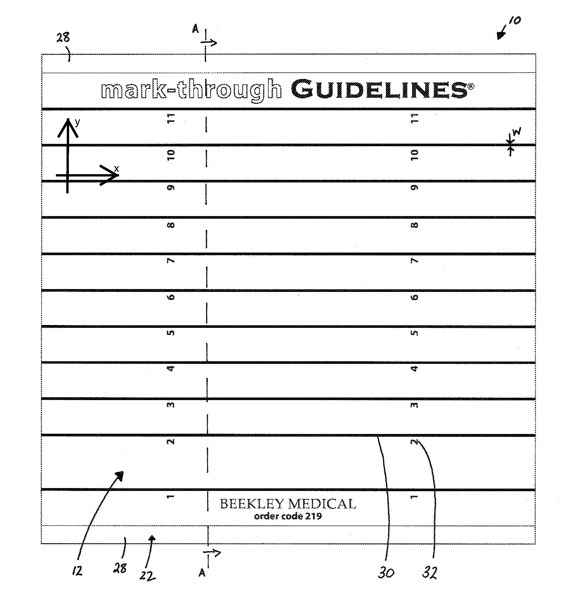
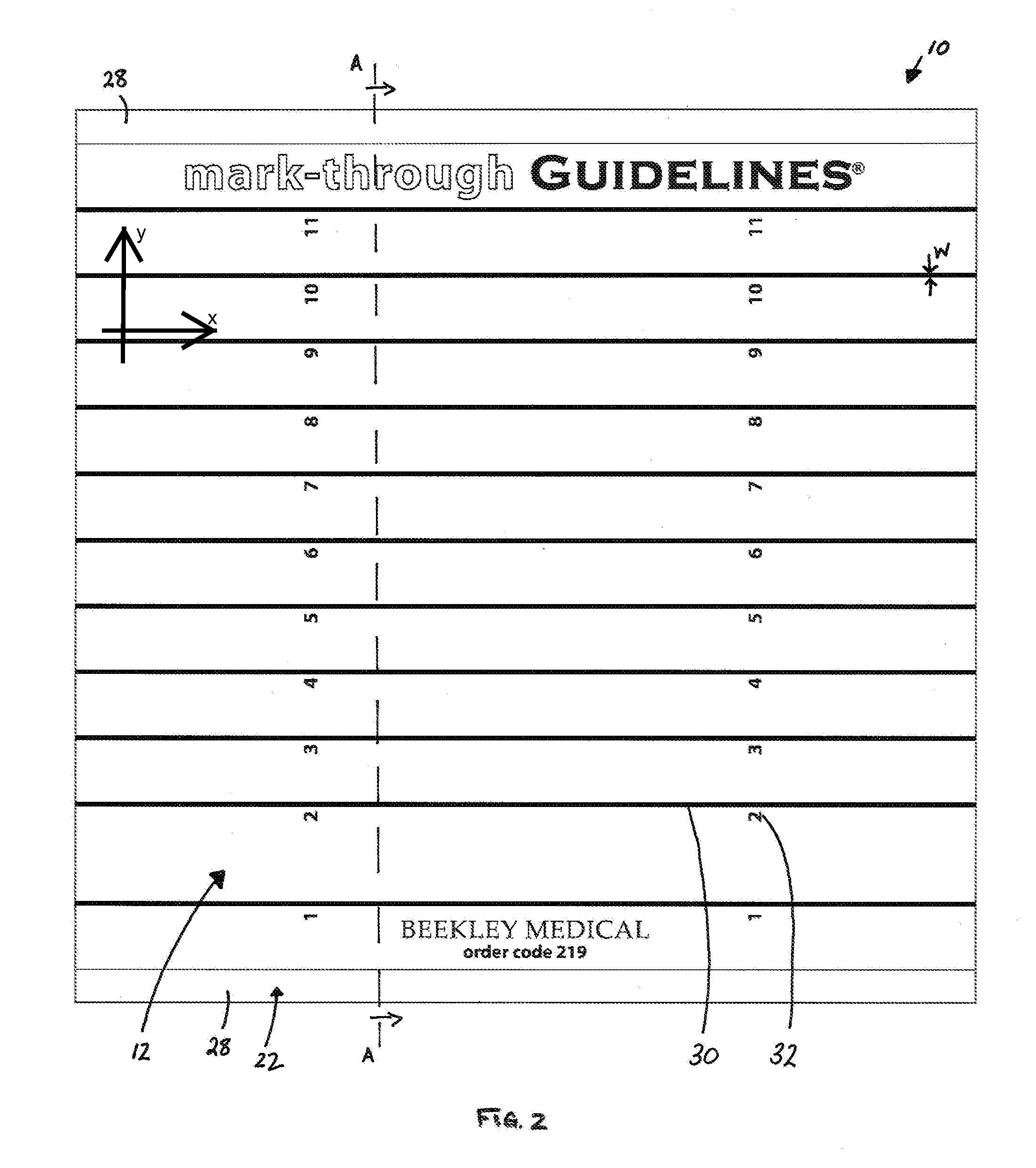
[0040]One advantage of the current inventive marking grid is that it allows a marking made substantially anywhere along the grid to transmit accurately, and at least in some embodiments, substantially simultaneously, to the underlying surface, such as, for example, a skin surface. Another advantage of the marking grid is that it is sufficiently flexible to conform to the contours of the skin surface when placed thereon, substantially without wrinkling, folding, buckling or distorting. Yet another advantage of the marking grid is that it remains attached and stays in place on the underlying surface until manually peeled away. These features allow for an accurate and efficient manner to register, i.e., localize, a needle entry site when performing a medical procedure, such as, for example, a CT-guided biopsy, with minimal inconvenience to the patient.

Problems solved by technology

This can impede the accuracy of the placement of the mark, because once the grid is removed, the doctor or technologist no longer has the visible grid lines to use as a reference point.
One problem the inventors recognized with such a grid is that the underlying surface cannot be marked at substantially any point.
Such marking may be detrimentally inaccurate, depending on the size of the internal point of interest, making the biopsy more difficult.
However, the inventors recognized that these grids still have several problems.
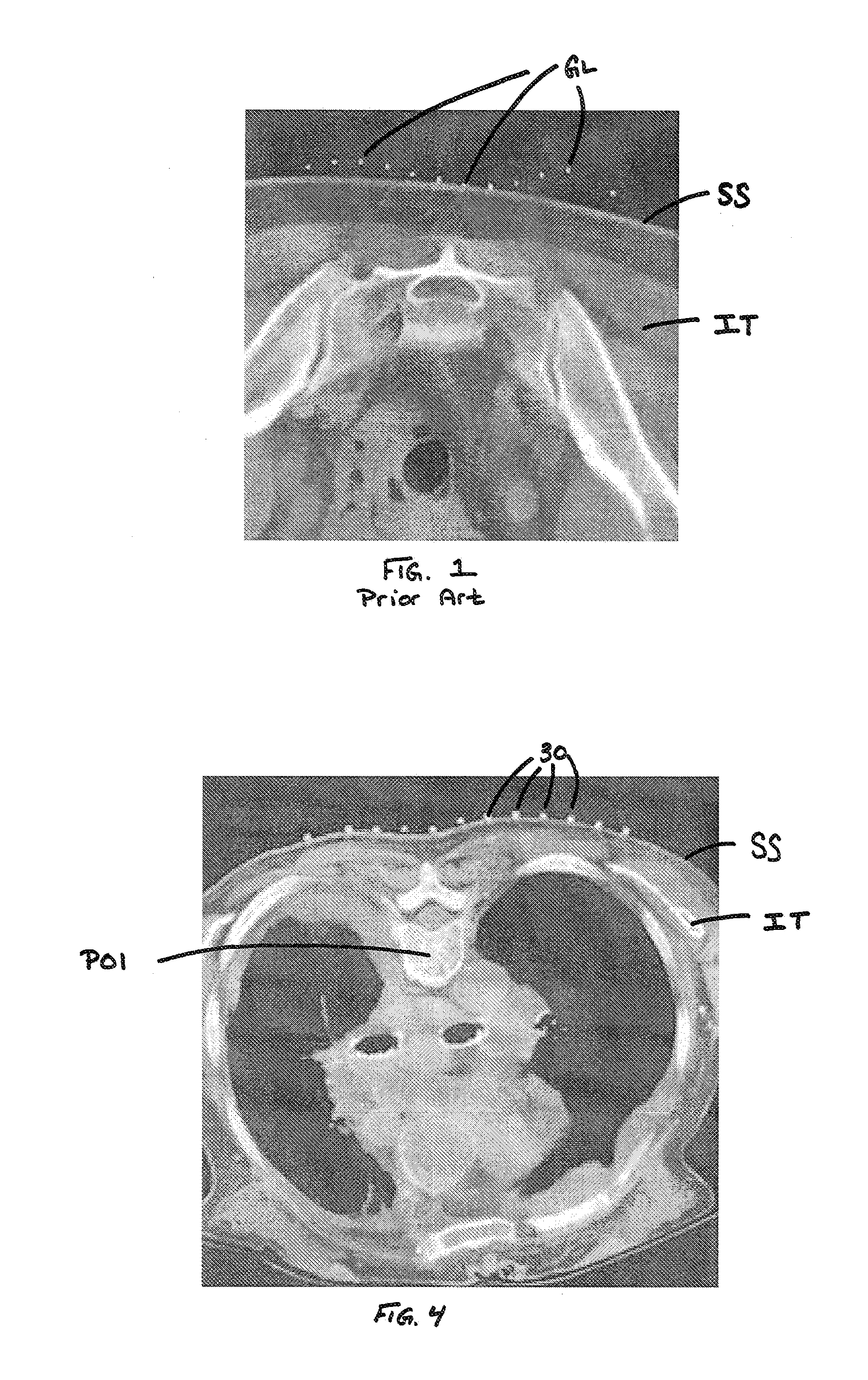
Between the ends, however, the device may not conform to the contours of the skin but rather leave gaps between the device and skin and / or cause wrinkling of the device.
This gapping makes it more difficult for the technologist to correctly correlate the area of interest with the patient's skin surface SS because the references in the image, i.e., the dots GL, are not at the skin surface.
Gapping also increases the risk of inaccurate or incomplete marking.
Another problem the inventors recognized with the thin adhesive strips is that the adhesive bond between the grid and the underlying surface is not very strong.
Accordingly, the grid is susceptible to inadvertent movement such as sliding on the skin or detaching from the skin, thereby causing inaccuracies in the marked locations.
Such inaccuracies increase the likelihood of having to repeat at least part of a procedure, such as, for example, a CT-guided biopsy, resulting in wasted time and materials, and more importantly, undue pain and discomfort for a patient.

Method used


Image

  • Skin Marking Porous Grid and Related Method of Use
  • Skin Marking Porous Grid and Related Method of Use
  • Skin Marking Porous Grid and Related Method of Use

Examples


Embodiment Construction

[0047]Embodiments of the invention are described herein in conjunction with the drawings provided herein. The embodiments disclosed herein are to be considered exemplary of the principles of the present invention described herein. Various modifications will be apparent to those skilled in the art based on the teachings herein without departing from the scope or spirit of the invention disclosed herein.

[0048]The term “pen” is used herein to mean without limitation any of various instruments for marking, writing or drawing with ink or a similar substance. In one embodiment, the pen has its own ink-source, and a tip made of porous, pressed fibers, such as felt. The term “marking medium” is used herein to mean any substance capable of marking, such as, for example, without limitation, ink or dye. The term “ink” is used herein to mean without limitation a fluid or viscous or other substance used for marking, writing or printing. One pen that can be used in connection with the present inv...


PUM


Abstract

An image guided biopsy grid markable with marking medium for marking a subject's skin underlying the grid with a marking to identify a needle entry target. The grid includes a flexible substrate and a plurality of substrate pores extending therethrough. An adhesive layer on the underside of the substrate conformingly and removably attaches the substrate to the skin substantially without gapping therebetween. The adhesive layer defines a plurality of adhesive pores and/or adhesive free spaces that allow marking medium to flow through the adhesive layer and onto the skin to mark the skin and identify the needle entry target. The biopsy grid may be marked substantially anywhere along its upper surface and marking medium will pass therethrough and mark the skin.

Description

FIELD OF THE INVENTION[0001]The present invention relates to marking grids, and more particularly, to marking grids placed on a patient's skin having the capability to transmit a marking medium through the marking grid and onto the underlying skin.BACKGROUND OF THE INVENTION[0002]It is common in the medical field for a doctor and / or technologist to need to correlate an internal area / point of interest appearing on a radiographic image or a scan of a patient with a location on the skin surface of the patient. For example, if a doctor finds a suspicious internal mass on an image or scan, the doctor may decide to biopsy such mass, i.e., remove a portion of such mass for further testing. In order to do so, the doctor must determine where to insert a biopsy needle at the skin surface in order to contact the mass below. Once that determination is made, the insertion point is marked on the skin. Typically, this is done with a type of marking medium, e.g., a permanent or semi-permanent ink, ...

Claims


Application Information

Patent Timeline
Patent Type & Authority Applications(United States)
IPC IPC(8): A61B10/02A61B6/00
CPCA61B90/39A61B6/12A61B10/0233A61B2090/3966
Inventor TRABOULSI, MAEGHAN E.JOHNSON, THOMAS A.
Owner BEEKLEY A CT
Why Eureka
Try Eureka