Augmented power-aware decompressor

a power-aware, decompression technology, applied in the direction of individual semiconductor device testing, testing circuits, instruments, etc., can solve the problems of limiting the level of test data compression, inability to encode test cubes, negligible probability of not finding a solution (or having an encoding conflict), etc., to reduce the toggling rate of decompressed test stimuli

Active Publication Date: 2014-04-03
SYNOPSYS INC
View PDF16 Cites 18 Cited by
  • Summary
  • Abstract
  • Description
  • Claims
  • Application Information

AI Technical Summary

Benefits of technology

[0019]Embodiments for constructing power-aware linear decompressors are described. The resultant decompressor scheme has 1) a diverse output space with fewer decompressor-imposed constraints than the simple decompressor schemes; 2) supports efficient dynamic encoding for early identification and resolving of encoding conflicts during ATPG; as well as 3) provides an efficient mechanism for reducing toggling rate in the decompressed test stimuli. As a result, the present invention provides an efficient mechanism for dynamic test pattern compaction and aggressive test data compression while improving WTM.

Problems solved by technology

A challenge for the combinational decompressors is that they encode all specified care bits in one shift cycle using only variables from the tester which are dedicated for this shift cycle.
The worst-case, most highly specified shift cycles tend to limit the level of test data compression because when the number of scan chains increases then the number of variables per shift cycle is sufficiently large to encode the most highly specified shift cycles.
If a solution does not exist then the test cube is unencodable.
However, if the number of variables is sufficiently larger than the number of specified care bits then the probability of not finding a solution (or having an encoding conflict) is negligible.
A challenge for the decompressor schemes using the dynamic reseeding is to maximize TDVR since fewer care bits are required at the end of test pattern set.
A challenge for the decompressor schemes using the static reseeding is to minimize time overhead because reseeding may delay shift operations.
A challenge for the decompressor schemes based on the test cube clustering is to reduce the bandwidth between the decompressor and the tester because the parent and control test sequences need to be repeated for each test pattern in a cluster.
High power dissipation during test may result in either overheating or supply voltage noise—either of which can cause a device malfunction leading to loss of yield, reliability degradation, or even permanent damage of the CUT.

Method used


Image

  • Augmented power-aware decompressor
  • Augmented power-aware decompressor
  • Augmented power-aware decompressor

Examples


example 1

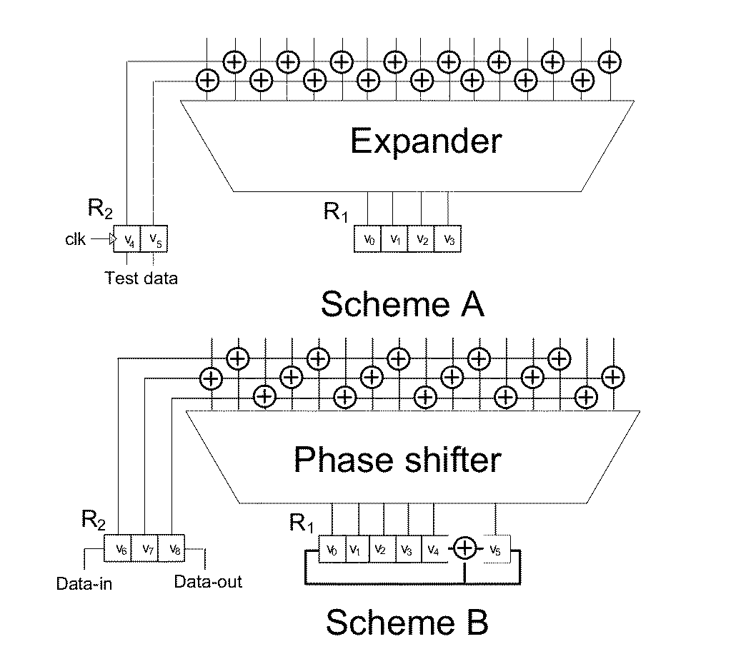
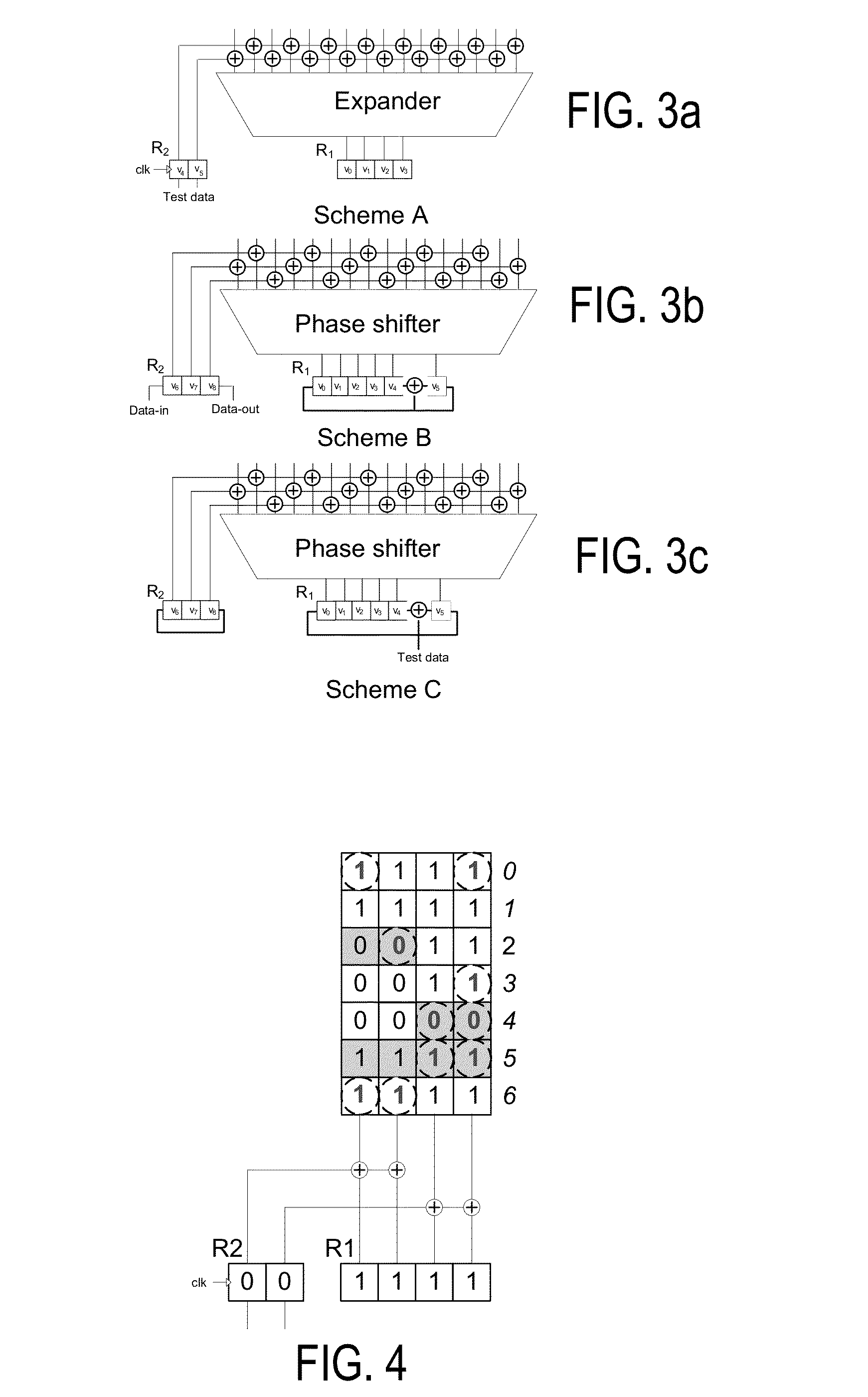
[0069]FIG. 3 illustrates embodiments of the present invention. More formally, scheme A is a block diagram of a power-aware decompressor comprising two registers R1 and R2 of length n and m, respectively. Register R1 periodically receives static variables (or static seeds) from the tester. Register R2 selectively receives dynamic variables (or dynamic seeds) from the tester. As a result, the dynamic variables have a limited scope (typically a few consecutive shift cycles) while static variables are typically valid for one test pattern or n shift cycles. Also, the scope of the dynamic variables (dynamic seeds) may change in wide range for each pattern while the scope of the static variables (static seeds) is typically fixed for the whole pattern set. Next, registers R1 and R2 are coupled to the scan chains of a CUT by a logic network (or XOR expander) such that register R2 defines a partition. As a result, dynamic variables divide scan cells in the CUT into groups such that each group...

example 2

[0070]FIG. 5 shows another embodiment of the power-aware decompressor comprising a periodically reloadable register R1 and a selectively reloadable register R2 having two segments S1 and S2. In this embodiment, each of the segments comprises two or more memory elements such that each of the segments can independently receive dynamic seeds from the tester. In this case, two dynamic seeds are required to encode the highlighted care bits. More precisely, in shift cycle 0, 4-bit static seed 1001 is loaded in register R1 and both segments S1 and S2 are initialized to 00. In shift cycle 4, dynamic seed 01 is loaded in segment S1. In shift cycle 5, dynamic seed 01 is loaded in segment S2. The encoding ratio for this case is 1.25 since the number of the specified care bits is 10 and the number of required variables from the tester is 8. Also, the toggling rate is 0.167 since the decompressed test stimulus includes 4 out of 24 possible transitions.

example 3

[0071]FIG. 6 shows another embodiment of the power-aware decompressor comprising a periodically reloadable register R1 and two selectively reloadable segments S1 and S2 of register R2. In this embodiment, only one of these selectively reloadable segments can receive a dynamic seed from the tester per shift cycle, such that segment S2 can receive a dynamic seed in the current shift cycle from the tester if and only if segment S1 received the previous dynamic seed, and vice versa. The encoding ratio and toggling rate for this embodiment are 1.25 and 0.167, respectively.


PUM


Abstract

Decompressor circuitry includes a first segment and a second segment each comprising memory elements (MEs) and (i) said first segment receives the plurality of static variables originating from the tester, and (ii) and said second segment, receives the plurality of dynamic variables originating from the tester.

Description

REFERENCE TO RELATED APPLICATIONS[0001]This application claims the benefit of U.S. Provisional Application No. 61 / 708,949 filed on 2 Oct. 2012.BACKGROUND[0002]1. Field[0003]The technology relates to electronic design automation in the integrated circuit industry. Various embodiments relate to test data volume and test application time reduction during testing of integrated circuits and more particularly for decompressing test stimuli and minimizing toggling rate in the decompressed test stimuli.[0004]2. Description of Related Art[0005]Electronic design automation (EDA) is applied in the semiconductor industry for virtually all design projects. After an idea for the product is developed, EDA tools are used to define a specific implementation including lithographic masks for production of the finished chips, in a process referred to as tape-out. The lithographic masks are then used with fabrication equipment to manufacture integrated circuit wafers. Testing and diagnosis are required ...

Claims


Application Information

Patent Timeline
Patent Type & Authority Applications(United States)
IPC IPC(8): G01R31/26
CPCG01R31/26G01R31/318335G01R31/318547
Inventor GIZDARSKI, EMIL
Owner SYNOPSYS INC
Why Eureka
Try Eureka