Accurate fluid level measurement device

a fluid level measurement and accurate technology, applied in the direction of liquid/fluent solid measurement, instruments, machines/engines, etc., can solve the problems of inability to meet some requirements, inaccurate, expensive, etc., and achieve the effect of simple and accurate methods of conversion

Inactive Publication Date: 2014-04-10
DEERE & CO
View PDF20 Cites 15 Cited by
  • Summary
  • Abstract
  • Description
  • Claims
  • Application Information

AI Technical Summary

Benefits of technology

[0011]The force measuring mechanism can convert a large change in fluid level into a much smaller position change, facilitating simple and accurate methods of converting fluid level to an electrical signal. The force measuring mechanism can include a spring coupled to the top of the float, a magnet coupled to the spring, and a Hall Effect sensor sensing the position of the magnet and generating an output related to the position of the magnet. The length of the float and the uncompressed length of the spring can be substantially the same as the distance between the fluid level for an empty tank and the fluid level for a full tank. By appropriately scaling the spring force and extent of spring compression, the spring can be fully relaxed with an empty tank and fully compressed with a full tank. The fluid level measurement system can include a microcontroller that receives the output of the Hall Effect sensor and computes the fluid level in the tank using the output of the Hall Effect sensor.

Problems solved by technology

Existing fluid level measurement devices (sometimes called “senders”) are typically either inaccurate, expensive, or have low resolution.
Accurate position measurement of the float over long distances is expensive.
Low accuracy and / or low resolution position measurement is less expensive, but may fail to meet some requirements.
This imposes a load on the battery and makes it impractical to have the sender operate continuously.

Method used


Image

  • Accurate fluid level measurement device
  • Accurate fluid level measurement device
  • Accurate fluid level measurement device

Examples


Embodiment Construction

[0017]For the purposes of promoting an understanding of the principles of the novel invention, reference will now be made to the embodiments described herein and illustrated in the drawings and specific language will be used to describe the same. It will nevertheless be understood that no limitation of the scope of the novel invention is thereby intended, such alterations and further modifications in the illustrated devices and methods, and such further applications of the principles of the novel invention as illustrated therein being contemplated as would normally occur to one skilled in the art to which the novel invention relates.

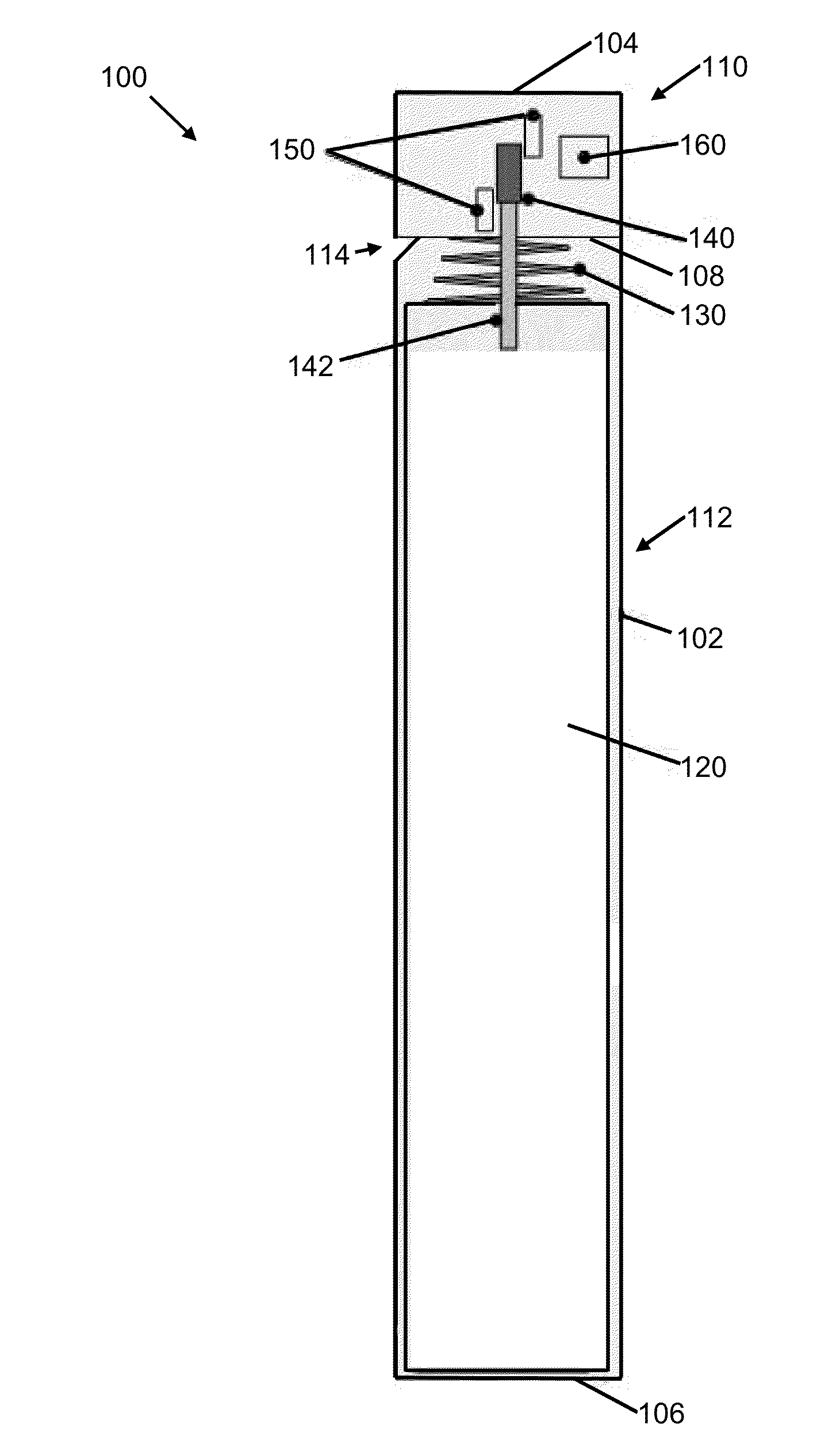
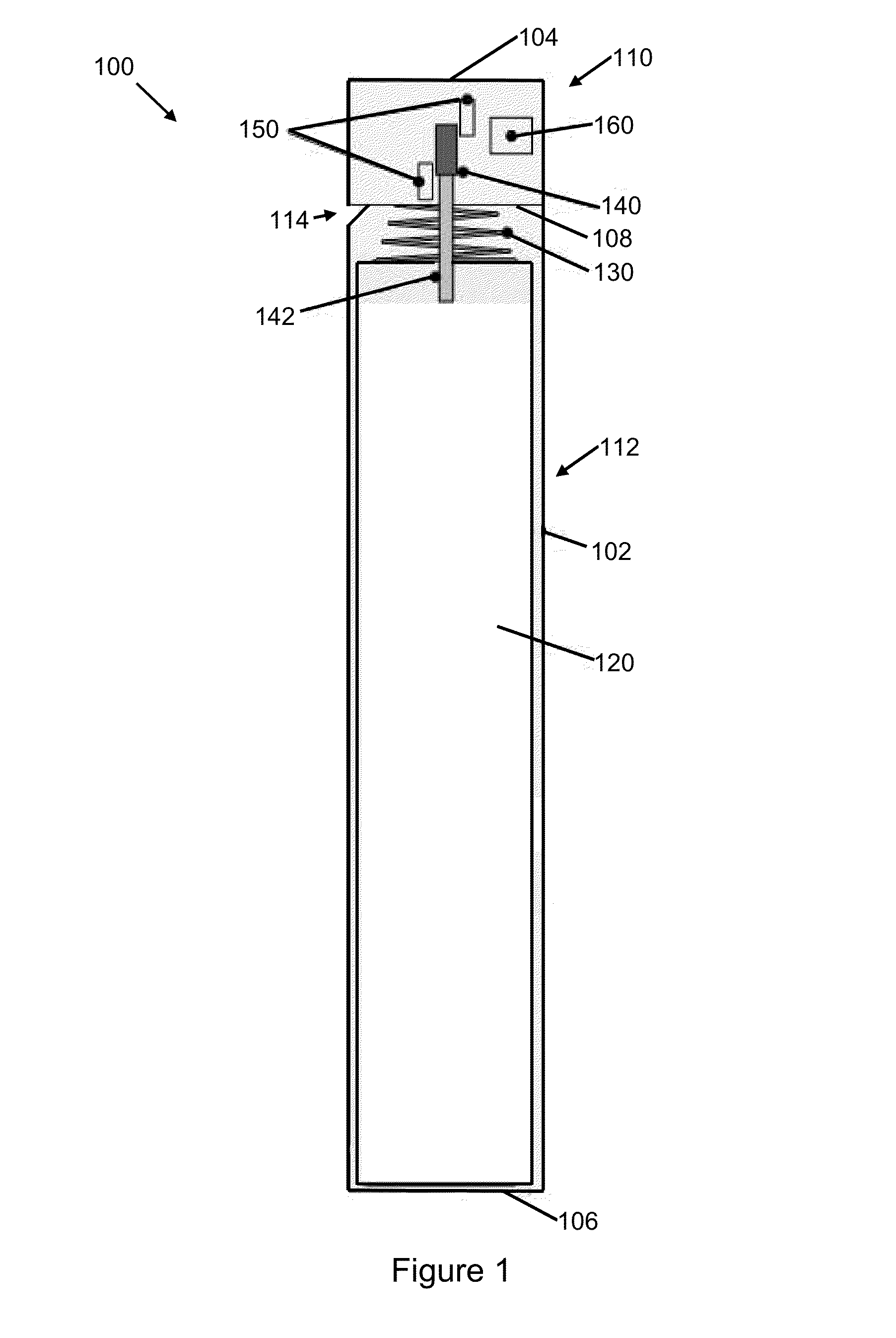
[0018]FIG. 1 illustrates an exemplary embodiment of a fluid level measurement device 100 comprising a tube 102, a float 120, a spring 130, a magnet 140, Hall effect sensors 150 and a controller 160. The tube 102 has a generally cylindrical shape extending from a top end 104 to a bottom end 106 of the tube 102. In this embodiment, the tube 102 includes a ...


PUM


Abstract

A fluid level measurement system for sensing fluid level in a tank is disclosed that includes a float that moves vertically in the interior of the tank, and a force measuring mechanism coupled to the float that generates an output based on the upward force on the float. The system can include an outer tube where the float is contained in the outer tube. A microcontroller can compute fluid level using the force measuring mechanism output. Altitude and other factors can be accounted for. Exemplary force measuring mechanisms can include a Hall Effect sensor sensing position of a magnet coupled to the float, or a force sensor coupled to the float. The length of the float, or the float and uncompressed spring can be substantially equal to the height of the tank. The float can have a generally uniform or non-uniform outside diameter.

Description

FIELD OF THE INVENTION [0001]The present invention generally relates to the field of fluid level measurement, and more specifically to a sensor system to accurately measure the fluid level in a tank.BACKGROUND OF THE INVENTION[0002]Existing fluid level measurement devices (sometimes called “senders”) are typically either inaccurate, expensive, or have low resolution. One example of the various uses of fluid level measurement devices is the measurement of fuel in a fuel tank. Most fuel senders utilize a float that floats on top of the fuel and a sensing mechanism to determine the position of the float.[0003]Some fuel sender embodiments use sensors having a long arm with one end of the arm coupled to a float and the other end of the arm coupled to a rotary potentiometer. In these embodiments, fuel level changes cause the float to move which causes the arm position to change and the sensed resistance changes with arm position. Other fuel sender embodiments have a long cylindrical tube ...

Claims


Application Information

Patent Timeline
Patent Type & Authority Applications(United States)
IPC IPC(8): G01F23/30
CPCG01F23/30
Inventor NICHOLS, BOYD M.MYERS, DAVIDKOESTLER, BENJAMIN P.MEYER, CHRISTOPHER J.
Owner DEERE & CO
Why Eureka
Try Eureka