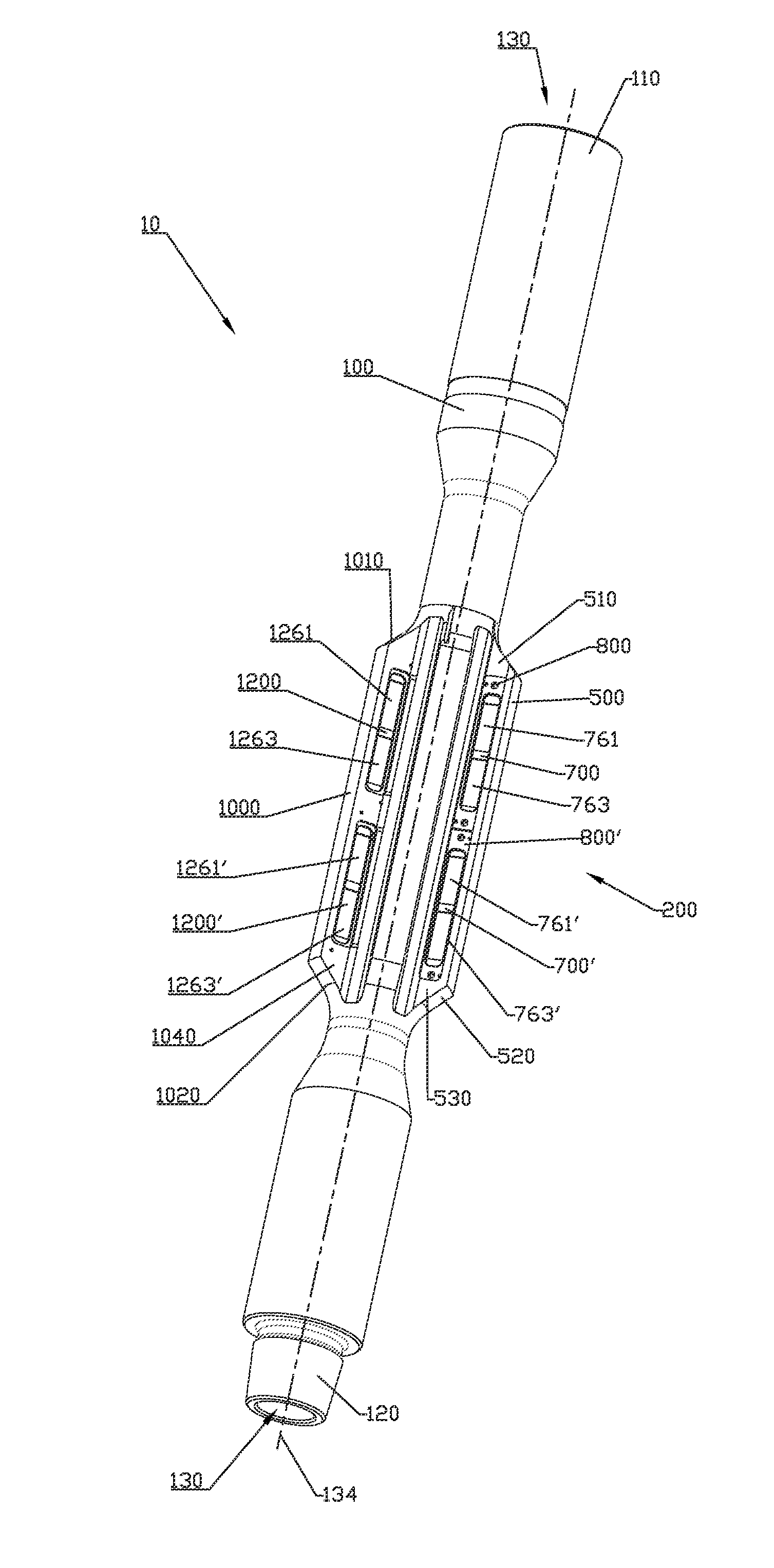
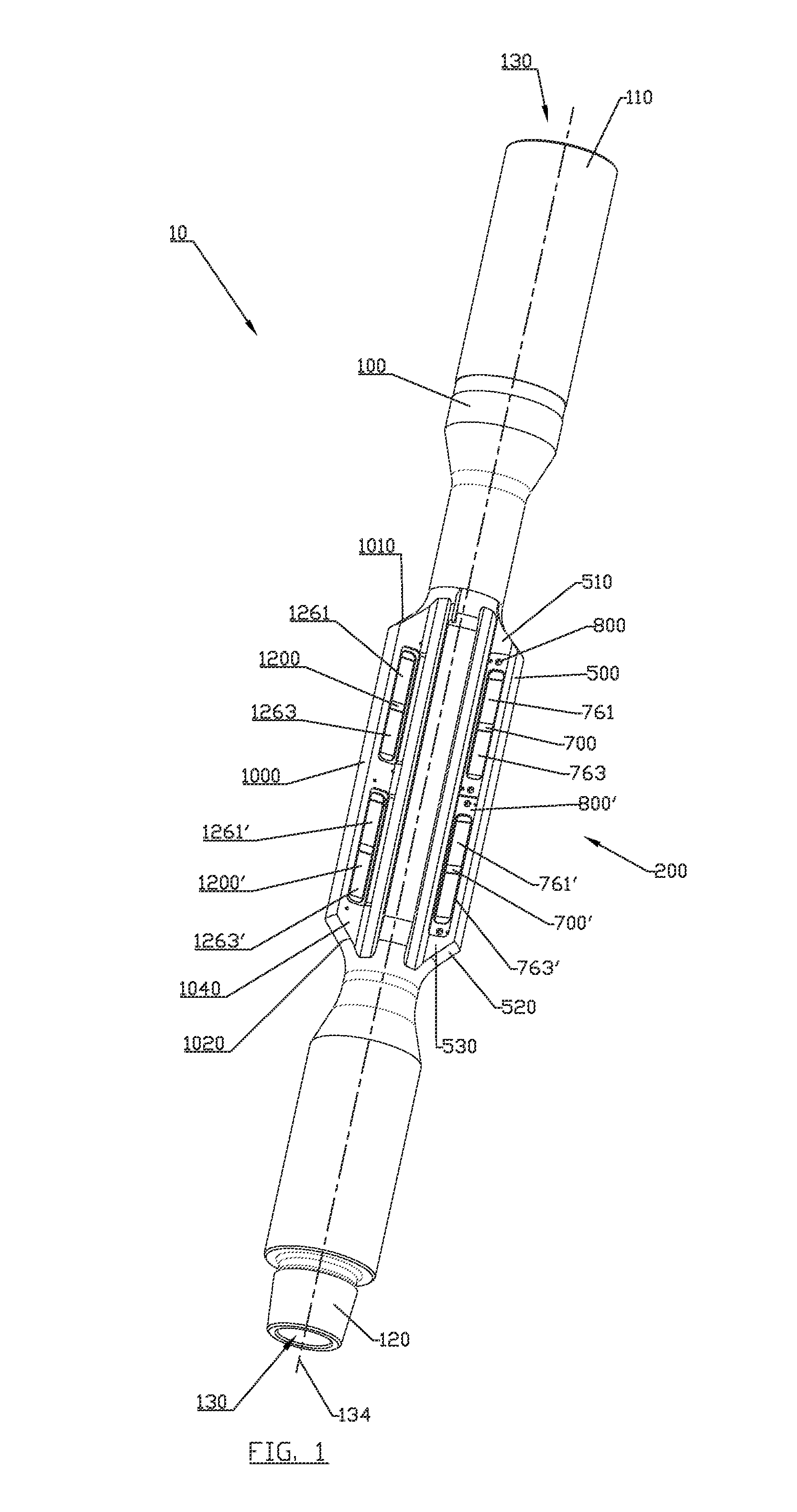
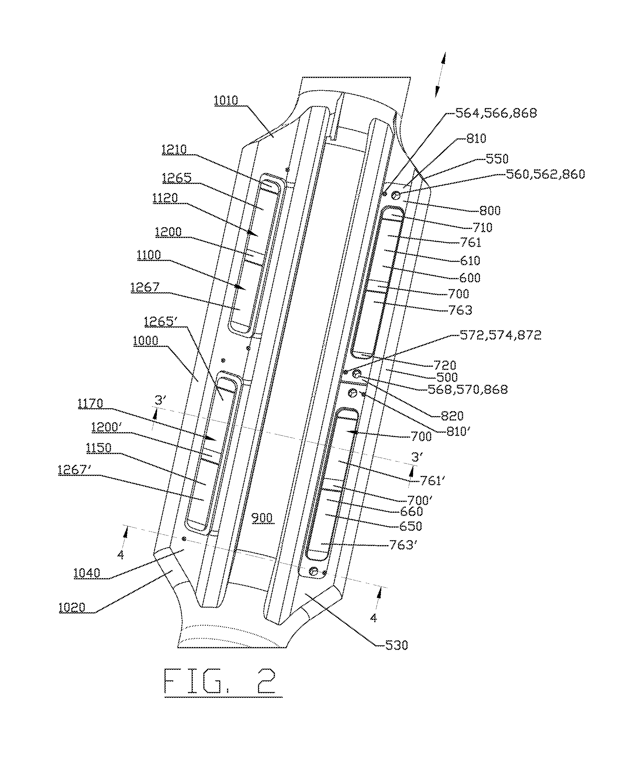
Downhole magnet, downhole magnetic jetting tool and method of attachment of magnet pieces to the tool body
a magnet and magnet body technology, applied in the field of wellbore cleaning tools, can solve the problems of metal debris entering the well, creating debris that becomes trapped in the wellbore, etc., and achieve the effect of preventing accidental removal
- Summary
- Abstract
- Description
- Claims
- Application Information
AI Technical Summary
Benefits of technology
Problems solved by technology
Method used
Image
Examples
second embodiment
[0139]FIG. 30 is a perspective view of magnet tool 10′ having various plurality of magnets in a plurality of magnetized longitudinal ridges 200 with the addition of a jetting sleeve 2500 where the sleeve is removable from the tool mandrel 2000. FIG. 31 is a side perspective view of magnet tool 10′. FIG. 32 is a sectional view of magnet tool 10′ taken through ridge 500. FIG. 33 is a sectional view of magnet tool 10′ taken through the section line 33-33 of FIG. 32. FIG. 34 is a sectional view of magnet tool 10′ taken through the section line 34-34 of FIG. 32. FIG. 35 is a sectional view of magnet tool 10′ taken through the section line 35-35 of FIG. 32.
[0140]Generally, magnet tool 10′ comprises tool mandrel 2000 with detachably connectable magnetized sleeve 2500. Sleeve 2500 can include a plurality of magnetized longitudinal ridges 200 (e.g., ridges 500, 900, 1000, 1400, and 1420) wherein the magnetized ridges have openings or pockets on either side of the ridges for magnets. Each of ...
third embodiment
[0175]FIG. 61 is a sectional of a magnet tool 10″ having magnets in valleys between longitudinal ridges (e.g., ridges 500, 900, 1000, 1400, and 1420) in a jetting sleeve 3000 where the sleeve is removable from the tool mandrel 2000.
[0176]FIG. 62 is a sectional view of magnet tool 10″ taken from section line 62-62 shown in FIG. 61. FIG. 63 is a sectional view of magnet tool 10″taken from section line 63-63 shown in FIG. 61.
[0177]FIG. 64 is a side perspective view of sleeve 3000 of magnet tool 10″ shown without magnets, spacers, and retaining plates.
[0178]FIG. 65 is a perspective view of a spacer 3700 which can be used with magnet tool 10″.
[0179]FIG. 66 is a perspective view of a retaining plate 3800 which can be used with magnet tool 10″.
[0180]FIG. 67 is a side perspective view of sleeve 3000 of magnet tool 10″ shown without retaining plate 3800. FIG. 68 is a side perspective view of sleeve 3000 of magnet tool 10″. FIG. 69 is a sectional view of magnet tool 10″taken from section line...
PUM
 Abstract
Description
Claims
Application Information
 - R&D
- Intellectual Property
- Life Sciences
- Materials
- Tech Scout
- Unparalleled Data Quality
- Higher Quality Content
- 60% Fewer Hallucinations
Browse by: Latest US Patents, China's latest patents, Technical Efficacy Thesaurus, Application Domain, Technology Topic, Popular Technical Reports.
© 2025 PatSnap. All rights reserved.Legal|Privacy policy|Modern Slavery Act Transparency Statement|Sitemap|About US| Contact US: help@patsnap.com


