Satellite with deployable payload modules

Active Publication Date: 2014-04-10
THALES SA
View PDF6 Cites 19 Cited by
  • Summary
  • Abstract
  • Description
  • Claims
  • Application Information

AI Technical Summary

Benefits of technology

[0013]A new satellite architecture implementing wide deployable payload modules is proposed by the present invention. The expected benefits of such an architecture are above all a capacity for carryin

Problems solved by technology

The increasing of the payload capacity of a satellite within the limits imposed by the nose cone of the launcher spacecraft remains an important issue.
This type of reflector which generates interference of the beam by the presence on the reflecting surface of uncontrolled reliefs related to the de

Method used


Image

  • Satellite with deployable payload modules
  • Satellite with deployable payload modules
  • Satellite with deployable payload modules

Examples


Embodiment Construction

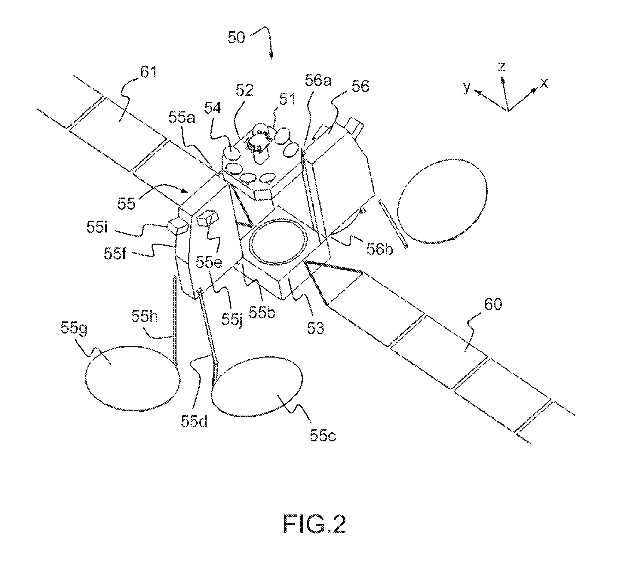
[0034]FIG. 2 represents an embodiment of a telecommunication satellite according to the invention. In this embodiment, a telecommunication satellite with geostationary orbit 50 comprises a rigid structure 51, an upper module 52 and a lower module 53. The upper 52 and lower 53 modules are secured to the rigid structure 51. In the operational configuration, the satellite being in its mission orbit, the rigid structure is oriented in a constant manner along an axis Z directed towards the earth. The upper module 52 and the lower module 53 form two ends of the structure along the Z axis. The upper module 52 is disposed as close as possible to the earth in the operational configuration. The lower module 53 is disposed as far as possible from the earth in the operational configuration. Stated otherwise, the upper module 52 is oriented towards the earth; the lower module 53 is oriented in a direction opposite to the earth. In a preferred implementation of the present invention, the upper mo...


PUM


Abstract

A telecommunication satellite with geostationary orbit comprises an upper module, a lower module, and a lateral module, disposed in a storage configuration between the upper module and the lower module, and deployed to an operational configuration of the satellite in the orbit by a rotation in relation to an axis Z oriented towards the earth in the operational configuration. The lateral module comprises two substantially plane and mutually parallel main surfaces, termed dissipative surfaces, able to dissipate by radiation a quantity of heat generated by facilities of the satellite; the dissipative surfaces being, in the operational configuration, held in a manner substantially parallel to the plane of the orbit, making it possible to limit the solar flux received by the dissipative surfaces and to optimize the quantity of heat dissipated by the lateral module.

Description

CROSS-REFERENCE TO RELATED APPLICATION[0001]This application claims priority to foreign French patent application No. FR 1202663, filed on Oct. 5, 2012, the disclosure of which is incorporated by reference in its entirety.FIELD OF THE INVENTION[0002]The present invention relates to the field of telecommunication satellites and more particularly it pertains to a satellite architecture comprising one or more payload modules deployable after a phase of launching the satellite.BACKGROUND[0003]A telecommunication satellite is placed in mission orbit by the combination of a launcher spacecraft and of its own propulsion means. According to a known technique, diverse service instruments and mission instruments are held against the structure of the satellite in a first configuration, termed the storage configuration. After separation with the launcher spacecraft, these instruments are deployed to an operational configuration allowing their operation. Thus, the implementation of solar generat...

Claims


Application Information

Patent Timeline
IPC IPC(8): B64G1/10G01S19/02B64G1/54
CPCB64G1/1007G01S19/02B64G1/54B64G1/222B64G1/44B64G1/503B64G1/223
Inventor CELERIER, BRUNO
Owner THALES SA
Why Eureka
Try Eureka