End cap of a lighting tube

a technology of end caps and lighting tubes, applied in the field of end caps, can solve the problems of rotatable led lighting tubes, reduced light-emitting diodes, high cost and complex assembly, etc., and achieve the effect of reducing the cost of producing end caps and reducing the assembly complexity of end caps

Inactive Publication Date: 2014-04-10
LEXTAR ELECTRONICS CORP
View PDF17 Cites 9 Cited by
  • Summary
  • Abstract
  • Description
  • Claims
  • Application Information

AI Technical Summary

Benefits of technology

[0022]The end cap may be applied to a rotatable end cap or a fixed end cap when the first assembly member is secured with the second assembly member in different ways. Therefore, the end cap can be applied to a rotatable lighting tube or a fixed lighting tube. In addition, the cost of producing the end cap and the assembly complexity of the end cap may be reduced because the first assembly member and the second assembly member have fewer components.

Problems solved by technology

When the temperature rises, the lighting efficiency and life span of light-emitting diodes decrease.
However, such a heat sink may limit the lighting angle of the LED lighting tube so that the LED lighting tube cannot emit light in all directions (i.e., 360 degrees) like the mercury lighting tube.
However, such a rotatable LED lighting tube includes several complex components to allow rotation of the LED lighting tube.
Therefore, the rotatable LED lighting tube has several problems such as high cost and complex assembly.
Thus, the manufacturer must invest much time and effort into producing the two kinds of the conventional end caps, as they cannot be interchangeably used by the rotatable lighting tubes and the fixed lighting tubes.

Method used


Image

  • End cap of a lighting tube
  • End cap of a lighting tube
  • End cap of a lighting tube

Examples


Embodiment Construction

[0032]In the following detailed description, for purposes of explanation, numerous specific details are set forth in order to provide a thorough understanding of the disclosed embodiments. It will be apparent, however, that one or more embodiments may be practiced without these specific details. In other instances, well-known structures and devices are schematically shown in order to simplify the drawings.

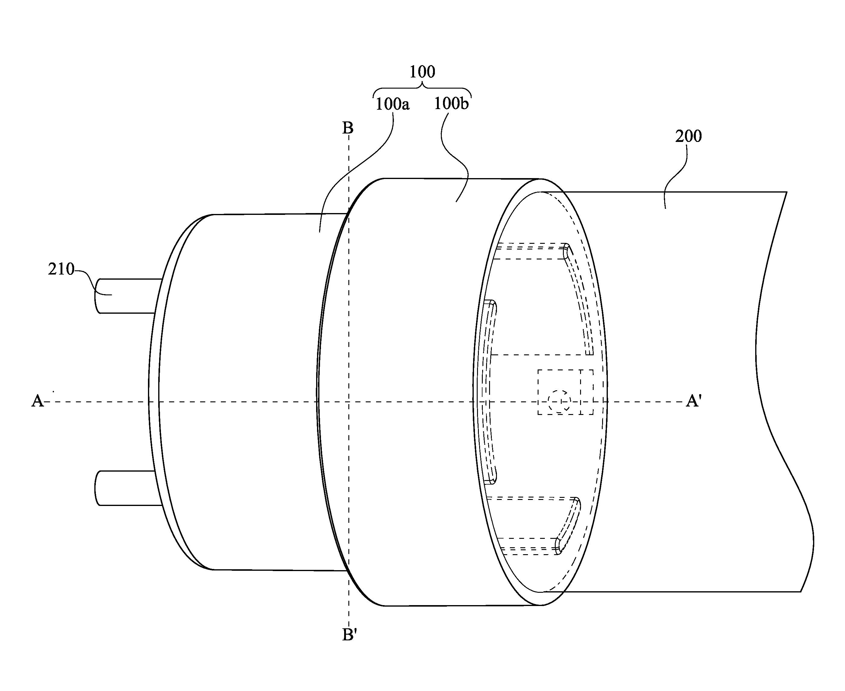
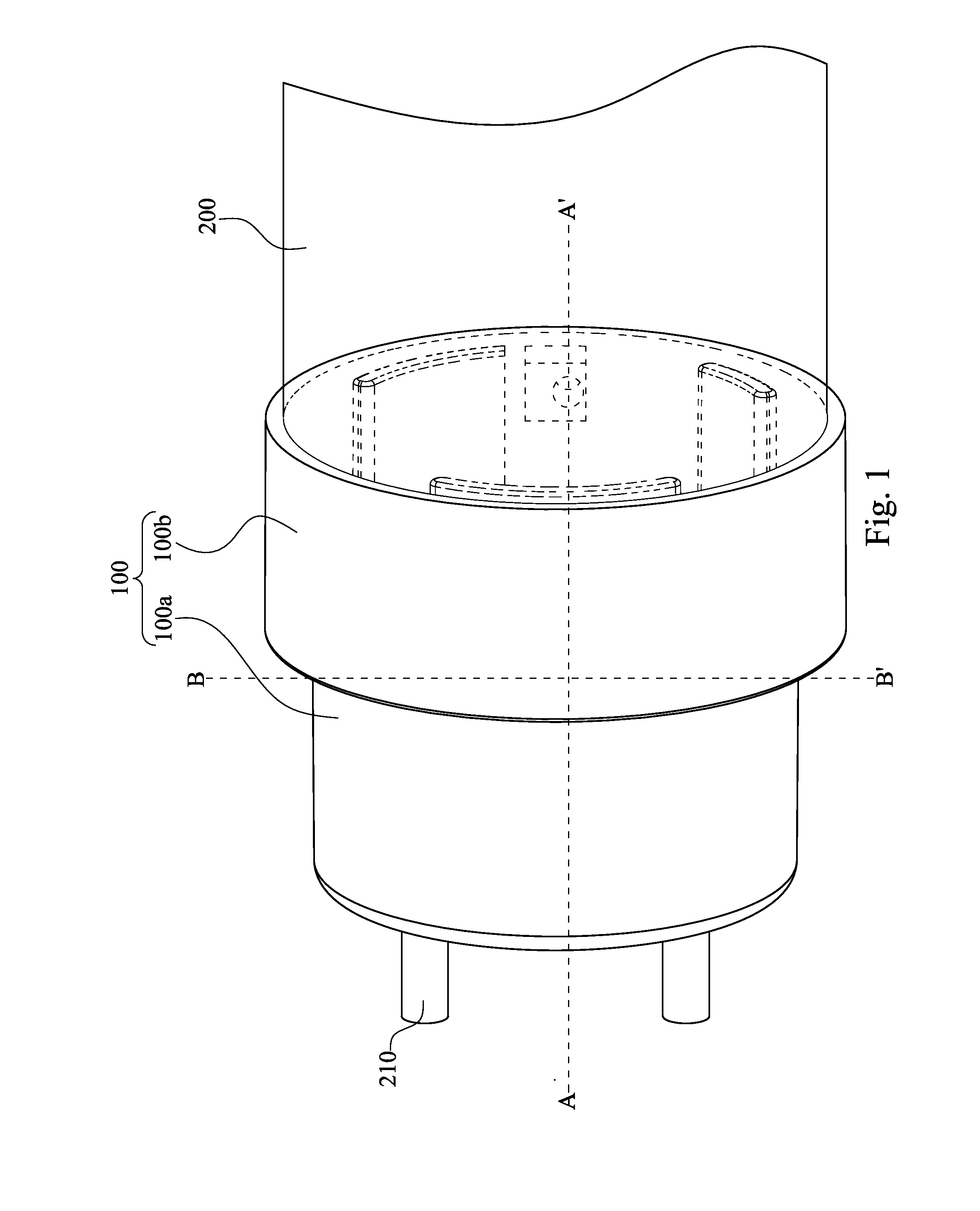
[0033]FIG. 1 shows a side view of an end cap 100 secured with a lighting tube 200 according to an embodiment of the present invention. An end of a lighting tube 200 is inserted into the end cap 100 such that the lighting tube 200 is secured with the end cap 100. After a connecting terminal 210 is extended through the end cap 100 and electrically connected to an external power source, the lighting tube 200 may operate to emit light using the electric power from the external power source. In this embodiment, a first assembly member 100a is secured with a second assembly member 100b t...


PUM


Abstract

An end cap of a lighting tube includes a first assembly member and a second assembly member. The first assembly member includes a first shell, several recesses, and two first position-limiting elements. The first shell has a first central-securing element, and the first shell forms a first area and a second area. The two first position-limiting elements are disposed on the first area. The second assembly member includes a second shell, a first elastic element, a second elastic element, and two positioning elements. An end of the second shell is connected to a lighting tube and a second central-securing element of the second shell is secured with the first central-securing element. The first elastic element is disposed on the second shell. The second elastic element is disposed on the second shell. The two positioning elements are disposed on the second shell.

Description

RELATED APPLICATIONS[0001]This application claims priority to Taiwan Application Serial Number 101136921, filed Oct. 5, 2012, which is herein incorporated by reference.BACKGROUND[0002]1. Field of Invention[0003]The present invention relates to an end cap. More particularly, the present invention relates to an end cap of a lighting tube.[0004]2. Description of Related Art[0005]Light-emitting diodes (LEDs) have many advantages such as high efficiency and long life. Therefore, traditional fluorescent tubes are gradually being replaced by LEDs.[0006]LEDs produce heat and high temperature during the conversion of electricity into light. When the temperature rises, the lighting efficiency and life span of light-emitting diodes decrease. Thus, there is a need to provide a heat sink in an LED lighting tube. However, such a heat sink may limit the lighting angle of the LED lighting tube so that the LED lighting tube cannot emit light in all directions (i.e., 360 degrees) like the mercury lig...

Claims


Application Information

Patent Timeline
Patent Type & Authority Applications(United States)
IPC IPC(8): F21V21/14
CPCF21V21/14F21K9/65F21Y2115/10
Inventor TSAI, MING-HUA
Owner LEXTAR ELECTRONICS CORP
Why Eureka
Try Eureka