Grounding device for welders

a grounding device and welder technology, applied in the direction of coupling device connection, coupling part engagement/disengagement, connection contact member material, etc., can solve the problems of inconvenient welding, potential damage to ground wire, and inability to easily remove and move without twisting

Inactive Publication Date: 2014-04-10
SAWYER MFG
View PDF7 Cites 10 Cited by
  • Summary
  • Abstract
  • Description
  • Claims
  • Application Information

AI Technical Summary

Benefits of technology

[0013]The grounding electrode generally comprises a stabilizing body having a long forwardly-protruding neck, two relatively short opposing legs, and a short tail section. Disk-like magnetic feet are attached distally at the ends of the two opposing legs. Both magnets are seated in a conforming metal cup oriented downward, open-faced, for magnetic anchoring of the body to a separate underlying grounding body. The cupped magnets are attached to the legs by spring-loaded screws inserted through pivot pins held captive in the legs, such that the magnetic feet can pivot through a range of angular orientations about the axis of the neck. The magnetic feet are fully insulated from the body. The pivoting ability allows the cupped magnetic feet to conform to irregular, e.g., cylindrical surfaces. In addition, the spring-loaded screws offer a range of tri-axial freedom such that the body remains free to see-saw about the legs. An adjustable and insulated set screw is threaded through the tail section and bears against the underlying ground body, taking advantage of the see-saw freedom to allow vertical adjustment of the height of the neck. This set screw includes a thumb screw atop the tail section to anchor a welder grounding lead (to earth ground). The elongate neck inclines upward, then horizontal, and then arches down along its length to serve as a carry-handle. A length-adjustable tungsten grounding electrode is carried at the distal end of the neck. The distal tip of the grounding electrode protrudes directly downward toward the earth structure and is tapered to a point. The forwardly biased see-saw bracket maintains the grounding electrode in direct contact with whatever earth structure the cupped magnets are affixed to, thereby ensuring a firm ground contact and reliable ground path for the welder grounding lead.

Problems solved by technology

However, the majority of these devices are permanently or semi-permanently attached to the workpiece and maintain the grounding electrode in a fixed relationship with the workpiece.
They cannot be easily detached and moved without twisting and potentially damaging the ground wire.
This is especially problematic when welding workpieces that must be rotated or moved during the process, such as pipes and cylinders.
This wrapping makes such welding inconvenient due to the need to unwrap the cable or to move the clamp periodically.
Moreover, this creates a safety hazard inasmuch as it diverts the welder's attention from his work to avoid twisting while the pipe is being rotated.
None of the foregoing or any other known prior art provides good, reliable electrical contact between a workpiece and welding apparatus despite irregularly-shaped workpieces, and despite repositioning of the ground electrode.

Method used


Image

  • Grounding device for welders
  • Grounding device for welders
  • Grounding device for welders

Examples


Embodiment Construction

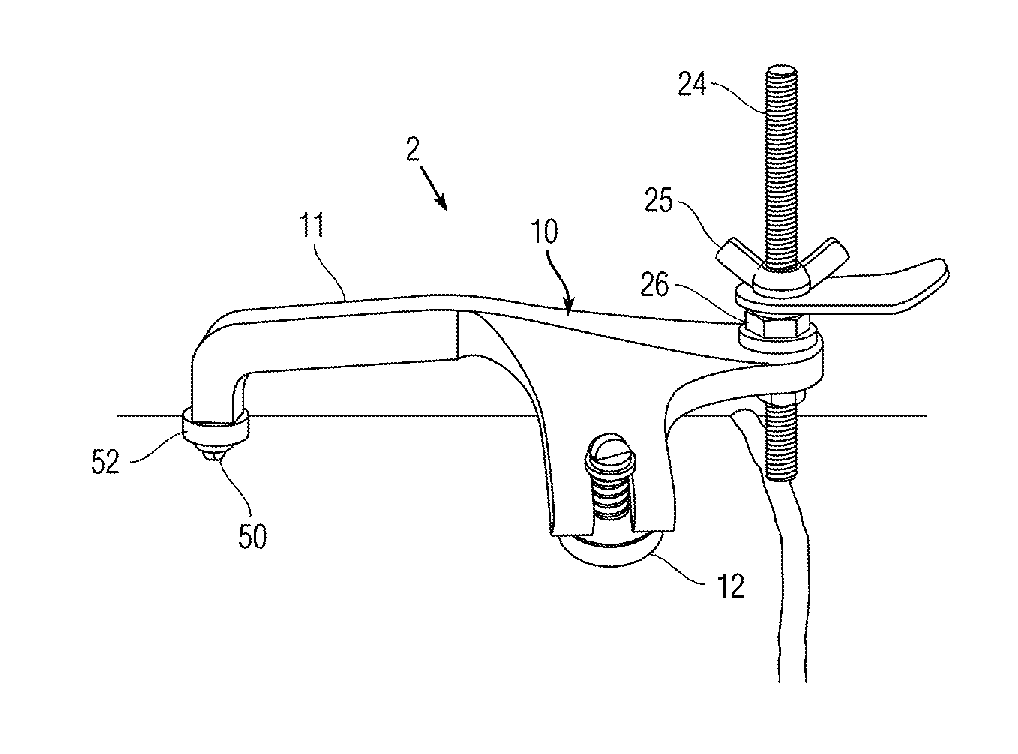
[0019]The present invention is a magnetic grounding clamp for portable vet secure connection of a welder grounding lead to earth ground using virtually any grounding body including irregular-shaped objects such as pipes and metal cylinders.

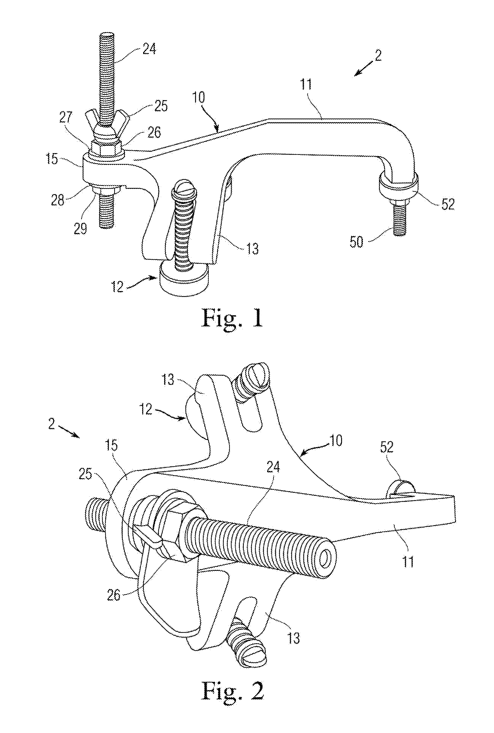
[0020]With collective reference to FIGS. 1-2, the magnetic grounding clamp 2 generally comprises a stabilizing body 10 having a long forwardly-protruding neck 11, two relatively short opposing legs 13, and a short tail section 15. A disk-magnetic foot assembly 12 is attached distally at the end of each leg 13. The body 10 is preferably formed as a unitary cast-aluminum member shaped as a quadruped, though other suitable material may exist. The legs 13 protrude perpendicularly on opposing sides of body 10 and are preferably angled (as shown) or arched downward therefrom slightly downward to provide elevation and to supinate the magnetic feet assemblies 12 slightly.

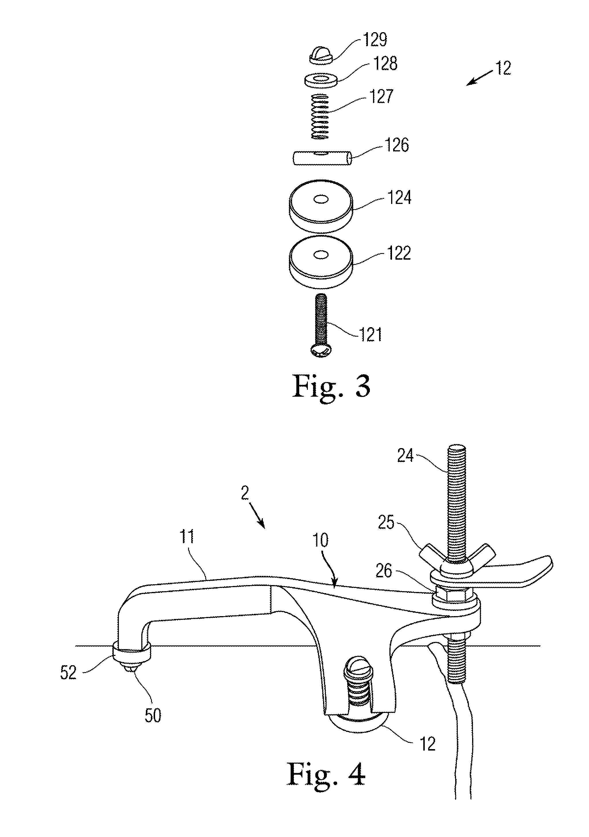
[0021]FIG. 3 is an exploded view of a magnetic foot assembly 12. Each magnetic foot 1...


PUM


Abstract

A magnetic grounding clamp for portable yet secure connection of a welder grounding lead to any grounding body including irregular-shaped objects such as pipes and metal cylinders. The grounding electrode generally comprises conductive body having a protruding elongate neck, opposing-protruding legs, and a pivoting foot assembly having a disk-like magnet attached distally at the end of each leg. A length-adjustable tungsten grounding electrode protrudes downward from the end of the elongate neck. The body has a tail section with an adjustable spacer protruding therefrom. The spacer see-saws the body about the foot assemblies to maintain the grounding electrode in direct contact with whatever earth structure the cupped magnets are affixed to, thereby ensuring a firm ground contact and reliable ground path for the welder grounding lead.

Description

CROSS-REFERENCE TO RELATED APPLICATION(S) [0001]The present application derives priority from U.S. provisional application Ser. No. 61 / 694,506 filed 29 Aug. 2012.FIELD OF THE INVENTION [0002]The present invention generally relates to welding accessories and more particularly, to a magnetic grounding electrode for quick-release connection of a welder grounding lead to earth ground using virtually any metal building frame including irregular-shaped objects such as metal tubes.DESCRIPTION OF PRIOR ART [0003]In electric welding, a workpiece being welded must be connected to the ground conductor or cable of an electrical welding apparatus. This is accomplished by means of a ground clamp connected to both the cable and the workpiece.[0004]Many clamping devices have been proposed to permit a ground wire to be removably affixed to a workpiece during the welding operation. However, the majority of these devices are permanently or semi-permanently attached to the workpiece and maintain the gr...

Claims


Application Information

Patent Timeline
Patent Type & Authority Applications(United States)
IPC IPC(8): H01R13/62
CPCH01R13/6205H01R4/64
Inventor HICKS, CHARLES E.HICKS, GINA MARIE
Owner SAWYER MFG
Why Eureka
Try Eureka