
System and method for internal pressurized gas drying of concrete

a technology of concrete and pressurized gas, which is applied in the field of systems and methods for drying concrete, can solve the problems of affecting the structural integrity and longevity of such structures, affecting the stability of concrete structures, so as to achieve the effect of lowering the internal relative humidity

Active Publication Date: 2014-04-10
STRUCTURAL GRP
View PDF28 Cites 6 Cited by
  • Summary
  • Abstract
  • Description
  • Claims
  • Application Information

AI Technical Summary

Benefits of technology

The patent describes a system and method for using pressurized gas to lower the humidity inside a concrete structure. The gas is forced into the structure through sealed cavities, which causes moisture to move towards the surface. A competitive inhibiting agent can be added to stabilize the existing gas against further detrimental expansion from the ongoing ASR. The technical effect is to provide a way to control the humidity inside concrete structures to prevent damage and improve durability.

Problems solved by technology

Moisture in concrete structures can have significantly negative effects on the structural integrity and longevity of such structures.
The reaction product, an alkali-silica gel, is hygroscopic, and will absorb water and swell if the concrete is in a moist environment.
The swelling of the gel can, under certain circumstances, lead to expansion and cracking of the concrete.
A sufficient supply of moisture is required in order for the gel to swell and to thus cause such negative effects.

Method used


Image

  • System and method for internal pressurized gas drying of concrete
  • System and method for internal pressurized gas drying of concrete
  • System and method for internal pressurized gas drying of concrete

Examples


Embodiment Construction

[0018]The invention summarized above may be better understood by referring to the following description, claims, and accompanying drawings. This description of an embodiment, set out below to enable one to practice an implementation of the invention, is not intended to limit the preferred embodiment, but to serve as a particular example thereof. Those skilled in the art should appreciate that they may readily use the conception and specific embodiments disclosed as a basis for modifying or designing other methods and systems for carrying out the same purposes of the present invention. Those skilled in the art should also realize that such equivalent assemblies do not depart from the spirit and scope of the invention in its broadest form.

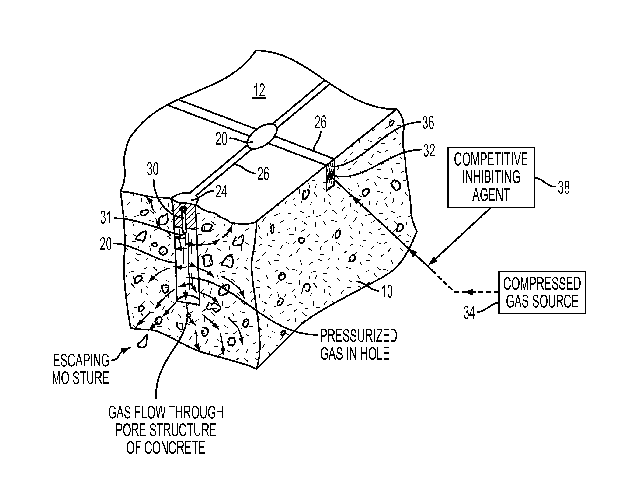
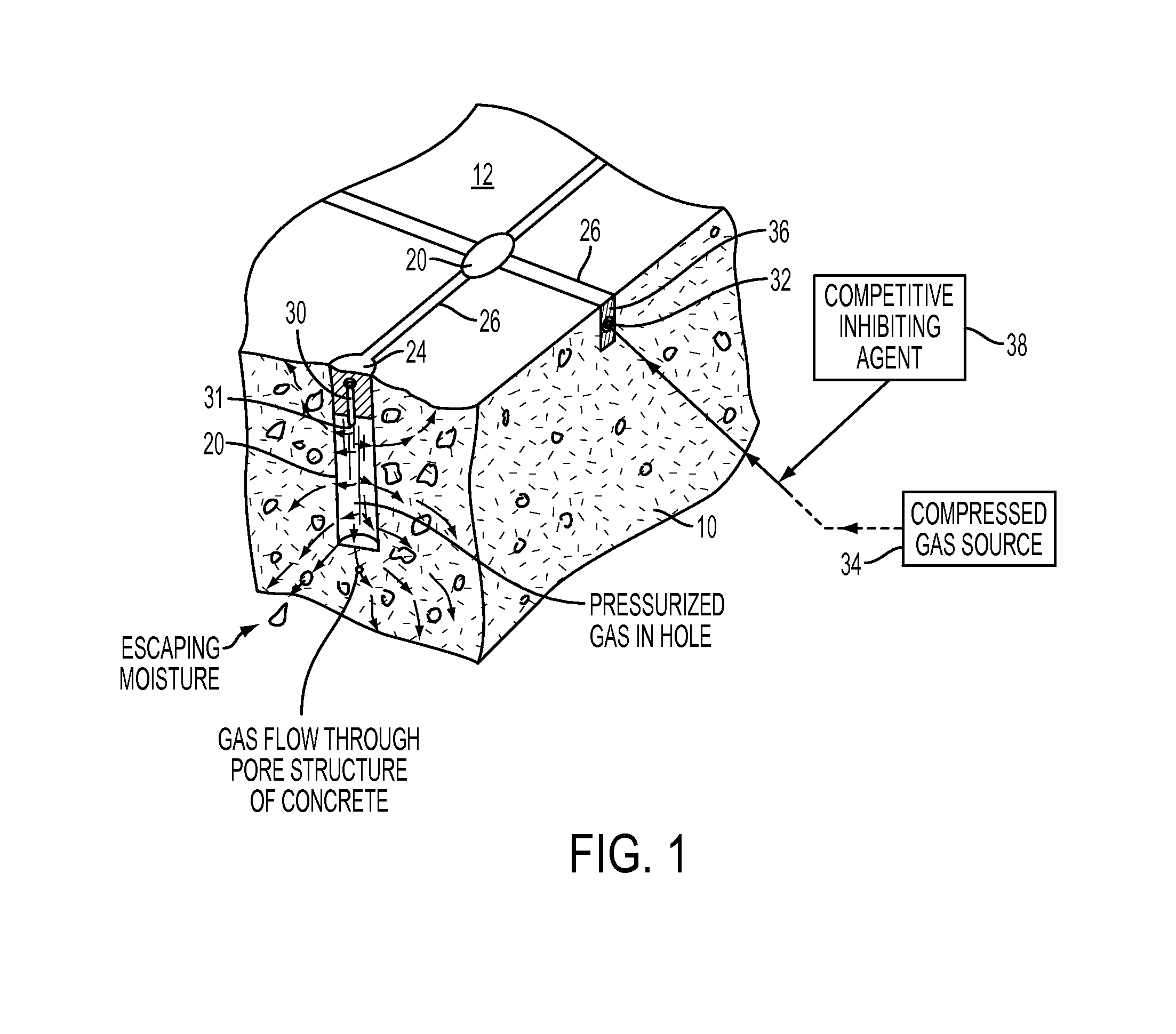
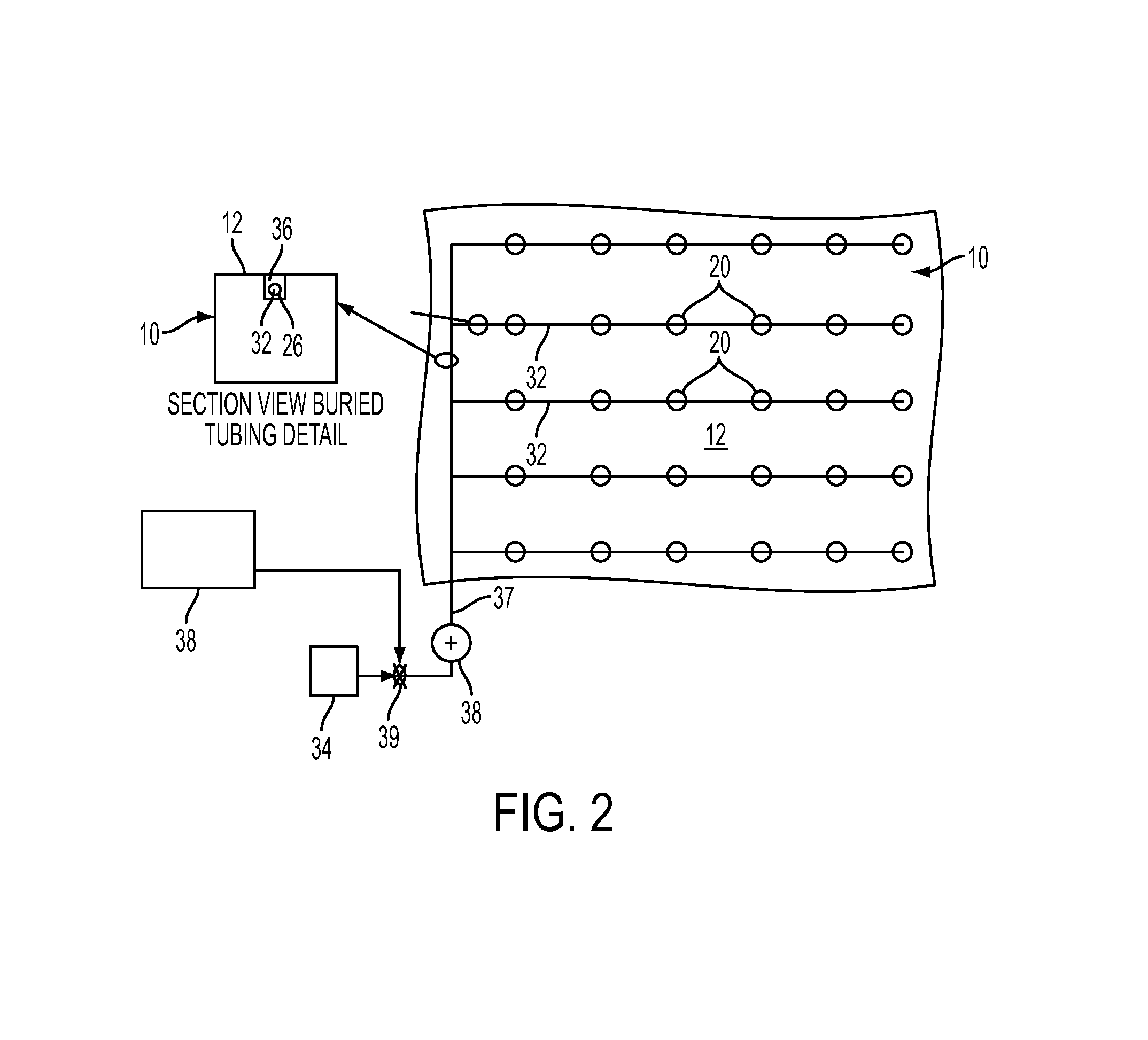
[0019]Disclosed is a system and method for lowering the internal relative humidity inside of a concrete structure by applying a pressurized gas and forcing such pressurized gas into the concrete structure, in turn driving moisture in the pores of the...


PUM

PropertyMeasurementUnit
humidity sensoraaaaaaaaaa
internal relative humidityaaaaaaaaaa
relative humidityaaaaaaaaaa

Abstract

A system and method are disclosed for lowering the internal relative humidity inside of a concrete structure by applying a pressurized gas and forcing such pressurized gas into the concrete structure, in turn driving moisture in the pores of the concrete to the exterior of the structure. Pressurized gas is supplied to a network of sealed cavities extending into the face of the concrete structure, ultimately causing the gas to move into the concrete structure through pores and capillaries through the structure, in turn driving moisture in the concrete structure toward the surface. Optionally, a competitive inhibiting agent, such as lithium nitrate, may also be provided to stabilize the concrete structure against future deleterious expansions caused by moisture uptake in the existing ASR gel.

Description

CROSS-REFERENCE TO RELATED APPLICATION[0001]This application is based upon and claims priority from co-pending U.S. Provisional Patent Application Ser. No. 61 / 744,919 entitled “Internal pressurized gas drying of concrete,” filed with the United States Patent and Trademark Office on Oct. 5, 2012, by the inventor herein, the specification of which is incorporated herein by reference in its entirety.BACKGROUND OF THE PRIOR ART[0002]1. Field of the Invention[0003]The present invention relates to systems and methods for drying concrete, and more particularly to a system and method for lowering the internal relative humidity inside of a concrete structure through application of a pressurized gas to drive moisture from the pores inside of such concrete structure.[0004]2. Background of the Prior Art[0005]Moisture in concrete structures can have significantly negative effects on the structural integrity and longevity of such structures. Alkali Silica Reaction, or “ASR,” causes concrete to sw...

Claims


Application Information

Patent Timeline
Patent Type & Authority Applications(United States)
IPC IPC(8): C04B41/00F26B21/00
CPCF26B21/003C04B41/00C04B41/009C04B41/5009C04B41/65F26B3/06C04B28/02C04B41/4529C04B2103/0008
Inventor EMMONS, PETER H.
Owner STRUCTURAL GRP
Learn More