Seal assembly

a technology of sealing assembly and seal, which is applied in the direction of sealing/packing, fluid removal, and wellbore/well accessories, etc., can solve the problems of preventing proper sealing of scssv or plug, and affecting the safety of the well

Active Publication Date: 2014-04-17
WEATHERFORD TECH HLDG LLC
View PDF8 Cites 1 Cited by
  • Summary
  • Abstract
  • Description
  • Claims
  • Application Information

AI Technical Summary

Benefits of technology

[0009]In one embodiment, the invention relates to an apparatus for use in a tubular, which may comprise a mandrel having a bore therethrough, a valve that is coupled to the mandrel, the valve selectively preventing fluid flow through the bore, and a seal assembly disposed around the mandrel. The seal assembly may include a compressible seal member and a piston assembly disposed on a first side of the compressible seal member. The piston assembly may include a piston head and a piston extension sealing member, the piston extension sealing member integrally formed with the piston head and extending at least partially between the mandrel and the compressible seal member. The piston assembly is movable to compress the compressible seal member from a first end, and the compressible seal member forms a seal with the tubular when the piston assembly moves toward the compressible seal member.

Problems solved by technology

The landing nipple within the tubing may become damaged by operations that occur through the nipple prior to setting the SCSSV or plug in the landing nipple.
Further, any debris on the inside surface of the nipple or any out of roundness of the nipple may prevent proper sealing of the SCSSV or plug within the nipple.
Operating the well without a safety valve or with a safety valve or plug that does not function properly presents a significant danger.
Thus, the current solution to conserve the safety in wells having damaged nipples includes an expensive and time consuming work over to replace the damaged nipples.

Method used


Image

  • Seal assembly
  • Seal assembly
  • Seal assembly

Examples


Embodiment Construction

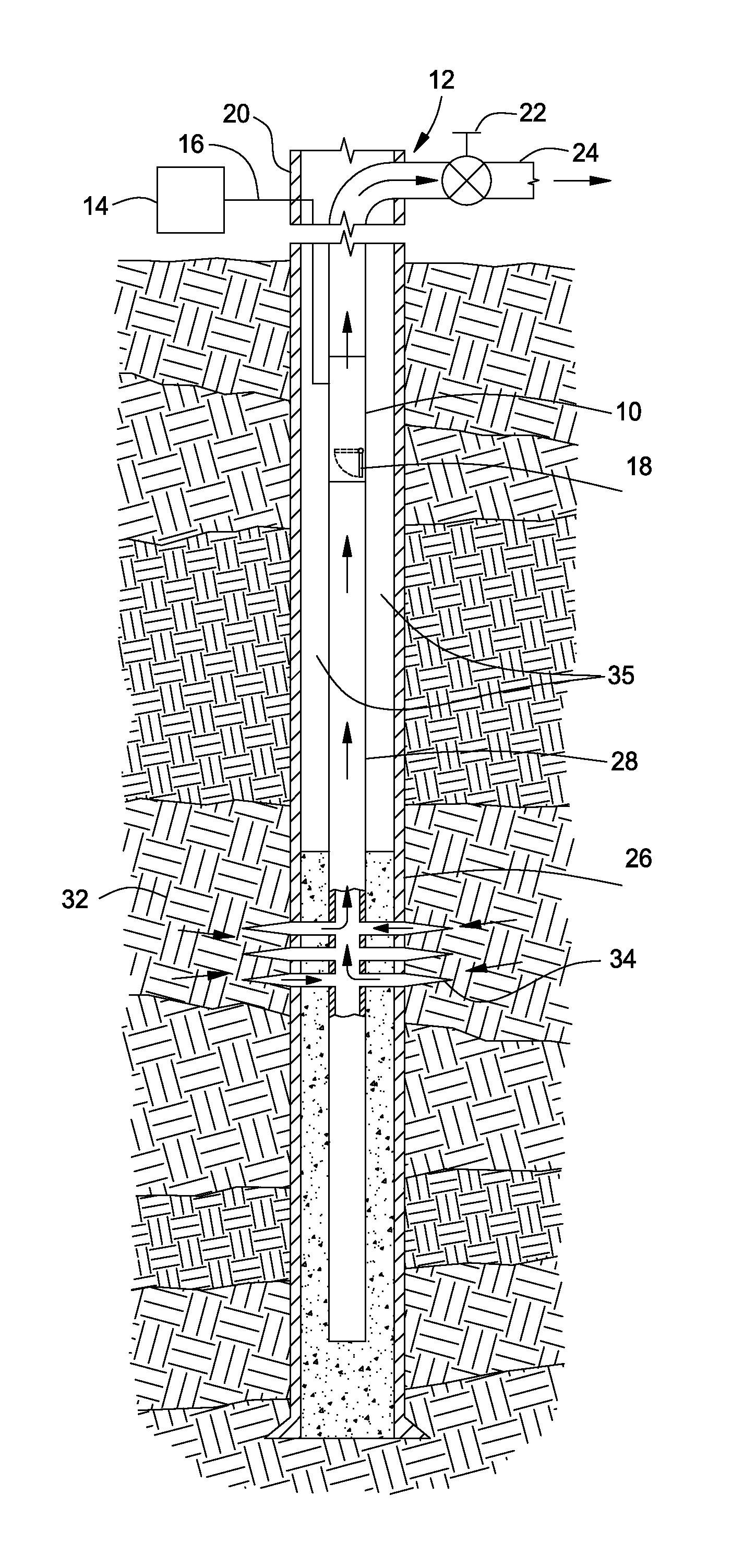
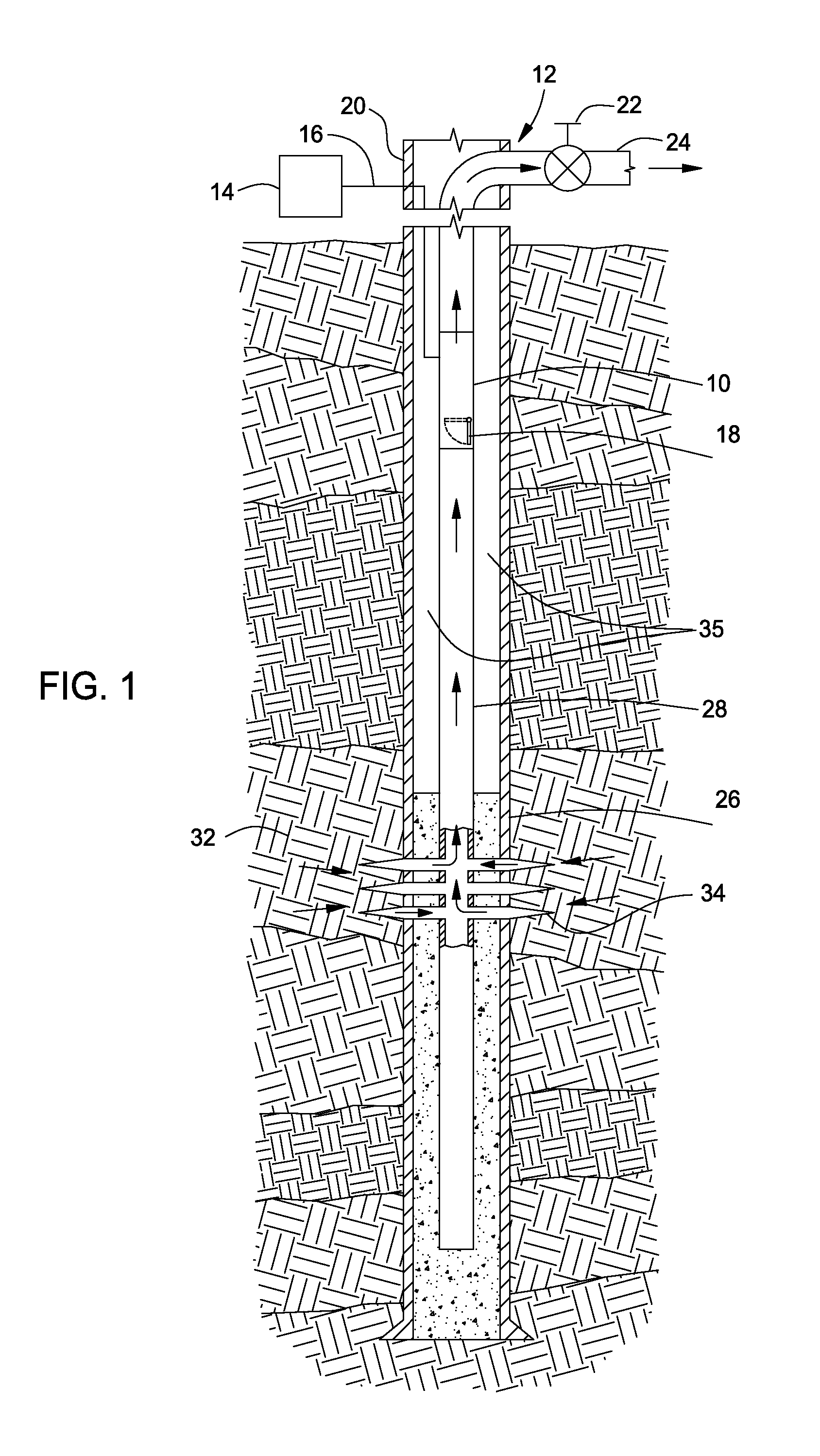
[0022]Embodiments of the invention generally relate to seal assemblies for any type of safety valve, dummy valve, straddle or plug designed to be landed and set within a tubular member. For some embodiments, the tubular member may form a ported landing nipple to enable fluid actuation of the safety valve, a side pocket mandrel, a sliding sleeve valve or a solid walled landing nipple. The seal assembly may be implemented with other variations of plugs, dummy valves, and subsurface safety valves different than exemplary configurations and designs shown and described herein since many operational details of these tools function independent of the seal assembly. For example, the seal assemblies may be used in all types of tools designed for landing in a nipple including wireline retrievable tools that may utilize flapper type valves or concentric type valves.

[0023]FIG. 1 illustrates a production well 12 having an SCSSV 10 installed therein according to aspects of the invention as will b...


PUM


Abstract

A seal assembly for use in a tubular includes a mandrel, a compressible seal member disposed around the mandrel, a first piston assembly in contact with a first end of the seal member, and a second piston assembly in contact with a second end of the seal member. The first piston assembly includes a piston head, and a piston extension sealing member integrally formed with the piston head, and extending at least partially between the mandrel and the compressible seal member. The compressible seal member forms a seal with the tubular when at least one of the piston assemblies is urged toward the compressible seal member.

Description

BACKGROUND OF THE INVENTION[0001]1. Field of the Invention[0002]Embodiments of the invention generally relate to tools having a seal assembly for sealing an annulus between a tubular seat in the wellbore and the outside of the tool disposed in the tubular seat.[0003]2. Description of the Related Art[0004]Surface-controlled, subsurface safety valves (SCSSVs) and plugs are commonly used to shut-in oil and / or gas wells. The SCSSV or plug fits into tubing in a hydrocarbon producing well and operates to block upward flow of formation fluid through the tubing. The tubing may include a landing nipple designed to receive the SCSSV or plug therein such that the SCSSV or plug may be installed and retrieved by wireline. During conventional methods for run-in of the SCSSV or plug to the landing nipple, a tool used to lock the SCSSV or plug in place within the nipple also temporarily holds the SCSSV or plug open until the SCSSV or plug is locked in place.[0005]Most SCSSVs are “normally closed” v...

Claims


Application Information

Patent Timeline
Patent Type & Authority Applications(United States)
IPC IPC(8): E21B33/128E21B34/10
CPCE21B34/10E21B33/128E21B34/105E21B33/1285
Inventor SMITH, RODDIE R.
Owner WEATHERFORD TECH HLDG LLC
Why Eureka
Try Eureka